Coppering a model
of the Flying Cloud
Scott Bradner
This article appeared in the December 2020 issue of the USSCMSG Broadside
History:
The British navy started experimenting with nailing copper sheets to the bottom of ship hulls to protect against ship worms and barnacles with the HMS Alarm in 1759.[i], [ii],[iii] The two year-long experiment was generally a success except that iron nails had been used to fasten the copper sheets to the hull and the nails has rusted out in some places causing some of the sheets to detach. A switch to copper alloy nails fixed that problem and the British navy adopted the use of copper sheets for many ships but they did not do so universally since copper was quite expensive. For a number of years debates raged in the English Parliament over the tradeoff between the expense of the copper and the expense of replacing or repairing hulls covered with barnacles or damaged by ship worms.[iv]
The first American ship to be coppered may have been the sloop-of-war Ranger in late 1777.[v] By the time the USS Constitution was built in response to the Naval Act of 1794 the coppering of hulls was common, at least for warships and whalers which undertook long voyages. Ironically, in the case of the USS Constitution the copper plates were imported from England.[vi]
The British navy settled on two standard sizes for the copper plates: 14” x 48” and 20” x 48” with the former size being the most common. Before the war of 1812 copper mined in the U.S was shipped to England for refining and forming into the plates needed for cladding ship hulls[vii] so the 14” x 48” size copper plate became the standard size in the U.S. as well. This size persisted even after America began producing its own copper plates.
overlap
Description:
An example of such a copper plate can be seen in figure 1 which shows one of the older, but not original, copper plates being ceremoniously removed from the USS Constitution to indicate the start of the latest restoration project.
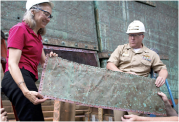
Figure 1: Copper
plate from the USS Constitution
You can see in Figure 1 that the plate is ringed with holes that are used to nail the plate to the ship’s bottom with copper-alloy nails. In addition, there is a pattern of holes inside of the edge holes these are for additional nails to ensure the copper plate is harder to dislodge once installed. You can also see that the bottom and left edges of the plate are not tarnished. That is because the edges of the plates are overlapped before being nailed to the hull to help ensure that the force of moving water does not dislodge the plates as the ship goes through the seas. In the case of the plate in the picture the top of a plate overlapped the bottom of the plate above it on the hull and the right edge of the plate overlapped with the left edge of the plate to the right of it. (See Figure 5 below.) In theory, the whole hull, or at least each side of the hull, would be consistent in which edges of a plate overlapped the plates around it but the reality of having multiple crews working simultaneously to copper a ship means that things were not consistent.[viii]
Figure 2 shows the original coppering of the 1835 ship Niantic recovered from San Francisco bay. A small section of the stern and lower rudder is on display in the San Francisco Maritime Museum.
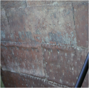
Figure 2 – Coppering from the Niantic
Figure 3 shows new copper sheets being installed on the USS Constitution.
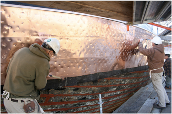
Figure 3 New copper on the USS Constitution.
Figure 4 is a plan for a copper plate.
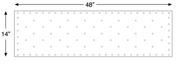
Figure 4: plan for a copper plate.
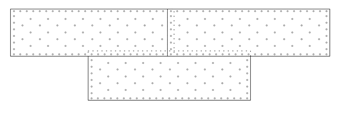
Figure 5: Shows how multiple sheets overlap when they are installed.
Figure 5 shows 3 sheets with the top edge of the bottom sheet being overlapped by the bottom edge of the two top sheets. The holes are lined up and the nails driven through both sheets to hold them to hull. Figure 5 also shows that the top right sheet overlaps the top left sheet in the same way. The three sheets are shown arranged as bricks are arranged in a wall but in the real world the alignment is not so regular. The overlap between the upper sheets is not generally centered above the lower sheets since the rows of sheets on the hull are of different lengths because of the curve of the hull. This causes the relationship between the rows of sheets to drift such that the upper overlap ranges across the length of the lower sheets.
Scale size:
As noted above, the most common size for the copper sheets used for coppering ships was 14” x 48” with an overlap of about an inch on one side and one end. That resulted in a size of 13” x 47”. At 1:96, which is the scale I am working in, that is very close to 1/8” x ½”.
In figures 1 & 2 you can see that the nail heads are quite small ¼ to ½ inch in diameter. Figure 3 shows larger dimples left by the hammer but figures 1 and 2 do not show such prominent dimples so they should not be assumed for a model. At 1:96 scale a ½” nail head is 5 thousandths of an inch across, very hard to see from even few inches away.
The copper plates used on ships of old were of different thicknesses depending on where on the hull they were being installed, with the copper being thicker near the bow.[1] The actual thickness ranged from 0.027 to 0.040 inches (22-28 ounce). At 1:96 scale that translates into about 0.3 mil to about 0.5 mil.
Commercial pre-made copper plates:
A word of caution. Some of the pre-made copper plates for use on model ships are quite poorly designed and way out of scale. Figure 6 shows one of these pre-made plates.
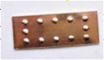
Figure 6: Pre-made copper plate
There are multiple things wrong with this plate. First the ratio is wrong- it should be 4 times as wide as it is tall. Second the dimples used to represent the nail heads are far far too big. Finally, this plate has dimples along all 4 sides (and no dimples in the center). This means that when installed you would have two rows of dimples between plates rather than the one that results from the plates being overlapped before the nails are installed. Not all pre-made plates are this bad. For example, Amati makes one style that is really quite good – see Figure 6. They are not perfect but they are far better than the one shown in Figure 6.
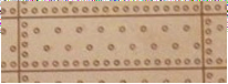
Figure 7: Amati pre-made copper plate.
Material:
I chose to use 1/8” wide by 1.0 mill thick adhesive backed copper foil tape that is made for use in stained glass windows. The particular brand I used was 3M VentureTape MasterFoil Plus Copper Foil. See Figure 8. From what I understand this is the same as the VentureTape MaterFoil tape since 3M bought VentureTape and added “3M” to the name. The tape under both names can be found at websites that cater to the stained glass crowd. I cut the strip into 4” inch long strips, which represents 8 sheets because I did not want to have to deal with individual 1/2” long pieces. I do not know how long the adhesive will last but I used the same material on another model that I coppered about 10 years ago and the copper on that model shows no signs of detaching. I did have a few places where the adhesive did not hold very well, for example where one strip overlapped another. In those cases, I used a small amount of contact cement to fix the problem.
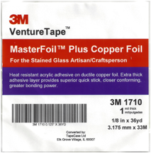
Figure 8: 3M Venture Tape copper foil tape
Pounce wheels
I made two different pounce wheels to make small dents in the copper foil to represent the nail heads and the dimples they sat in. The pounce wheels made dents that are significantly larger than the 5 thousandths of an inch that would be correct for scale but I am after a good visual impression rather than scale purity.
The first “edge” pounce wheel used a Gyros 81-10805 - 7/8”
diameter, 120 tooth mini circular saw blade made for Dremel tools. See Figure 9. With 120 teeth and a diameter of 7/8” the dents this pounce
when makes are 2.2” apart at 1:96 scale, very close to what the actual spacing
was on the full-sized plates.
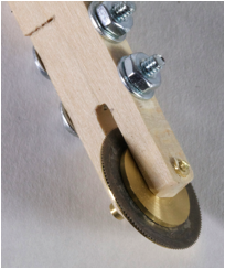
Figure 9: Edge pounce wheel
Because the blade is very thin, I turned stabilizers for each side. The one you can see on top of the blade in figure 9 supports the inner half of the blade and is about 1/16” thick. The stabilizer you can almost see on the other side supports almost the full diameter of the blade and is about 0.02 inches thick. I made a simple handle for the pounce wheel out of a stick of wood.
The second “center” pounce wheel was made using three Gyros
81-20715 - 3/4” diameter, 36 tooth blades separated by .018 thick shims. See Figure 10.
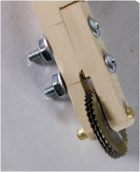
Figure 10:
Center pounce wheel
You can see that the teeth of the three blades are offset such that the tips of the inner blade teeth fall between the teeth of the outer two blades, which are aligned. In addition, I filed down the edges of the blades so that the teeth come to points rather than lines. I did this by mounting the blades on a spindle in a mini lathe and using a file on one side of the tooth part of the blades. The dents that these blades make are about 6.25” apart in scale, which is a little long for the center nail heads in addition, there are only 3 rows but I think that the wheel still gives a reasonable impression of the pattern used on the full-sized sheets.
Jigs
I then made three jigs to guide the pounce wheels when embossing the copper strips. The first jig, shown in Figure 11, was to guide the first “edge” pounce wheel along the edge of the copper foil strip.
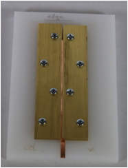
Figure 11: Edge guide jig
I used 1/8” brass and ¼” plastic to make the jig. The bottom edges of the brass plates were notched to create a channel slightly wider than 1/8” to hold a 4” long strip of the copper foil tape. the notches are sized to align the copper strip very slightly under the left brass plate, just enough so that if you run the edge pounce wheel along the slot between the brass plates it will make a row of dents along the edge of the copper strip. The pounce wheel is run through the slot with the smaller stiffener to the left so that the blade runs along the left brass plate. The brass plates are positioned such that the slot is just wide enough for the edge pounce wheel to fit through. The notch in the right-hand brass plate is sized so that the copper strip fits snugly in the resulting channel. As you can see in the figure, the slot winds up positioned over the edge of the copper strip. One could also use wood to build the jig but if you do, you should still bolt the jig together since the adhesive comes off the copper foil strip and gums up the guide slot from time to time and you need to take the jig apart to clean it out.
The second jig is to guide the other “center” pounce wheel along the center of the copper strip. This is shown in figure 12.
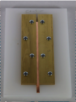
Figure 12: Center guide jig
This jig was constructed like the edge guide except the notches where sized to hold the copper strip such that when the center pounce wheel was run between the brass plates the rows of dents in the copper strip were between the edge row of dents on the left and the edge of the foil strip on the right. This can be seen in the figure. The gap between the two brass plates was sized so that the center pounce wheel just fit between them.
The third jig was used to create the crosswise rows of dents to indicate the end of one plate and the start of the next. This jig is shown in figure 13.
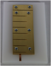
Figure 13: Transverse guide jig
For this jig I milled a slot along the underside of the 1/8” brass plate that was about 5/32” wide and 1/16 high so that the copper strip would slide easily into it. I then cut slots across the brass plate ½” apart. These slots were sized so that the edge pounce wheel would just fit. The top small piece of 1/8” brass served as a stop so that the copper strip did not go too far.
Tools:
I also use 3 different tools. The first tool is a modified scriber. I filed down the point so that it would be very sharp and would fit in the slot in the edge guide. This is shown in Figure 14.
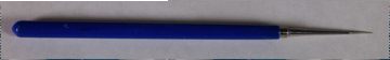
Figure 14: modified scriber “the puller”
You could just as easily make this tool out of a sewing needle stuck into a small dowel and it would work just as well.
The second tool is an Aanraku Foil Burnisher that I use to flatten the foil strip multiple times during the process. It is a hard plastic roller with no give. It is shown in Figure 15.
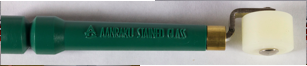
Figure 15 Aanraku Foil Burnisher
The third tool is a Sound Deadening Application Rolling Wheel Roller with a pliable plastic roller. I modified it by cutting down the roller to be about ¼” wide. I use it to secure the foil strip to the hull. It is shown in Figure 16.
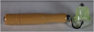
Figure 16: Sound Deadening Application Rolling Wheel Roller
All three of these tools are available through Amazon.
Procedure:
Now its time to make some strips of embossed plates.
First cut a pile of 4” long strips of the copper foil tape. Then rolled each of them flat using the foil burnisher. I used a small piece of window glass as the backing for this and the rest of the flattening steps below.
Once you have a pile of flattened copper foil strips you put each of them into the edge guide jig one by one. I used the puller scribe to pull them into the slot. It makes a tiny hole in the foil but that will be lost in the many dents that will get put in the strip. After the strip is in the gig, run the edge pounce wheel along the side to make the row of edge dents. After each strip has been embossed with the edge dents remove it with the puller scribe and roll it flat with the foil burnisher. You need to do this flattening step after each embossing step because the strip will get stuck in the next jig otherwise.
After all of the strips have their edge dents and have been flattened, slide them one at a time into the center guide jig using the puller scribe. When the strip is properly positioned run the center pounce wheel along the slot in the jig to make the center dents in the strip. As each of the strips is done remove it with the puller scribe and flatten it with the foil burnisher.
When all of the strips have had both their edge and center dents embossed and have been flattened, put them one by one into the transverse guide jig. The strip should just slide in but you can use the puller scribe to nudge it along if needed. The end of the strip should be tight up against the stop when its fully installed. Then run the edge pounce wheel along each of the saw cuts in the jig and along the slot at the end to emboss the transverse lines of dents. As before, use the foil burnisher to flatten the strip when it comes out of the transverse guide jig. When done the strip should have no raised bumps and the dents should be quite small. The resulting strips should look like the ones in figures 17 and 18.
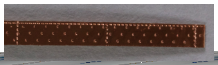
Figure 17: Close up of two sheets in a foil strip.
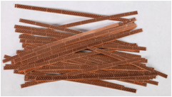
Figure 18: A pile of finished strips
I prepared the hull for installing the strips by spray painting the whole hull the color that is used above the waterline and, after that paint dries, spray the area to be coppered with copper colored paint. This last step means that any gaps between the installed copper foil strips will be harder to spot.
The strips are then cut to length and, where two strips intersect, cut to the right shape. The backing paper is removed from the strips and the strips are carefully applied to the hull. I then use the Sound Deadening Application Rolling Wheel Roller to adhere the strips to the hull and to shape the strips to fit the hull contour.
I used the guidance in the coppering chapter in Campbell to determine the pattern to follow when installing the strips. You should take care to butt the strips as close together as you can without overlapping them, both horizontally and vertically. Where the strips come together, as shown in figure 19, you want to be sure that there is a single row of the fine dents between them. In the same idea, there should be a row of fine dents along the top of the coppering between the copper and the part of the hull above the water line. You may have to make some special strips with both edges embossed to get this right. Just run the strip through the edge guide jig twice, flipping it end for end between times. You can see an example of such a strip just above the diagonal strips in figure 19.
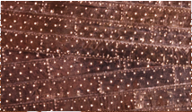
Figure 19: Intersecting copper strips.
Bow, stern and keel.
Campbell details how the bow. stern and keel were coppered. In particular the copper sheets on the bow and keel vertically oriented instead of horizontally. I used ¼” wide tape for the bow, using a ruler to guide the edge pounce wheel along both edges and free handed the center pounce wheel. See figure 20.
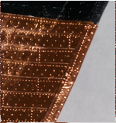
Figure 20: Bow
I used ½” tape for the stern and keel. In both cases the copper sheets were wrapped perpendicularly to the edges and the ½” wide tape is the right size to simulate a set of parallel 13”x48” sheets. I used a piece of 1/8” wide stock to guide the edge pounce wheel across the copper foil strip to simulate multiple side by side sheets. Then free handed the center pounce wheel between the rows of dents. This can be seen in Figure 21 which shows both the stern and the keel, with the keel covered by a false keel outside of the copper sheets as described by Campbell.
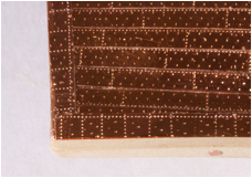
Figure 21: Stern and keel, showing false keel
The final result is shown in figure 22. I covered the entire hull with clear semigloss spray lacquer to protect the copper from tarnishing. In my case I want the model to represent the Flying Cloud just before she left on her first voyage so I left the copper untarnished but if you want your model to represent a craft that has been in the water a while you can manually tarnish the copper using a tarnishing solution made for model railroaders before coating it.
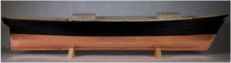
Figure 22: The finished coppering job.