Flying Cloud
built by
Donald McKay
launched
April 15, 1851
by Bruce M. Lane
Introduction to the web version
Bruce M. Lane developed this
manuscript in the 1950s and 1960s.
He deposited a copy in the Peabody Essex Museum
Library in 1967.
I
tracked Mr. Lane down in 2013 based on a footnote in Margaret Lyon and Flora Elizabeth Reynolds, The Flying Cloud and Her First Passengers. Via email he said that all of his Flying Cloud materials were packed into
boxes in preparation for him selling his house but gave me permission to get a
copy of the manuscript from the museum.
But it turned out that museum policies limit the amount of material that
can be copied from any one work to 10 pages at a time so obtaining a copy from
the museum was infeasible. I did view the manuscript in the library reading
room in August 2013 and found that it is now faded and
fragile. I let Mr. Lane
know this.
Two years later in July 2015 Mr. Lane
contacted me to say that he had uncovered his copy of the manuscript and
offered to send it to me so I could copy it. I took him up on his offer and scanned and OCRed the
manuscript. I met with Mr. Lane in
person in September 2015 and showed him some pages of the resulting material,
edited to fix OCR errors and reformatted for better presentation. Mr. Lane gave me permission to post
this copy of his manuscript. I
have only included Mr. Lane’s original illustrations and those images where I
found copies on the Internet that appeared to be out of copyright.
Mr. Lane told me that he had not found
a copy of Henry Hall’s Notebooks
for shipbuilding in the United States, 1881-1883 - Volume II, Models and Measurements when he
wrote the manuscript so some of the information in the manuscript is incorrect.
This document is copyright © Bruce M.
Lane 1967 and 2016.
Scott
Bradner, May 2016
Table of Contents
I. Introduction........................................................................................................... 12
II. Clipper Ship Era.................................................................................................. 14
III. Donald Mckay.................................................................................................... 16
IV. History of the Flying
Cloud.............................................................................. 26
V. Construction of the Flying Cloud.................................................................... 47
1. LAYING OFF.................................................................................................... 54
2. HULL CONSTRUCTION.............................................................................. 56
1 KEEL................................................................................................................... 56
2 SHOE.................................................................................................................. 61
3 MAIN KEELSON............................................................................................ 62
4 SISTER KEELSONS........................................................................................ 65
5 STEM, APRON, STERN TOST, INNER POST, DEADWOOD........... 66
6 SQUARE FRAMES.......................................................................................... 68
7 BULWARK STANCHIONS......................................................................... 73
8 CANT FRAMES............................................................................................... 75
9 KNIGHT HEADS............................................................................................ 76
10 HAWSE PIECES............................................................................................ 76
11 STERN FRAMING....................................................................................... 77
12 GARBOARDS................................................................................................ 78
13 BOTTOM PLANKING................................................................................ 80
14 WALES............................................................................................................. 84
15 PLANKSHEER.............................................................................................. 84
16 BULWARK PLANKING............................................................................. 86
17 MAIN RAIL.................................................................................................... 87
18 MONKEY RAIL............................................................................................. 88
19 FLOOR CEILING.......................................................................................... 89
20 LIMBER STRAKES....................................................................................... 90
21 BILGE KEELSONS....................................................................................... 90
22. HOLD CEILING.......................................................................................... 91
23 HOLD STRNGER......................................................................................... 92
24 LOWER DECK BEAMS............................................................................... 93
25 BETWEEN DECK WATERWAYS............................................................ 94
26 BETWEEN DECK CEILING...................................................................... 97
27 UPPER DECK CLAMPS.............................................................................. 97
28 UPPER DECK BEAMS................................................................................. 97
29 UPPER DECK WATERWAYS................................................................... 98
30 DECK FRAMING.......................................................................................... 99
31 HATCHES.................................................................................................... 101
32 MAST HOLES.............................................................................................. 102
33 SKYLIGHTS................................................................................................. 102
34 BITTS.............................................................................................................. 103
35 DECK PLANKING..................................................................................... 105
36 KNEES........................................................................................................... 107
37 HOLD STANCHIONS.............................................................................. 110
38 BETWEEN DECK STANCHIONS......................................................... 111
39 POINTERS AND HOOKS........................................................................ 111
40 HULL ORNAMENTAL WORK............................................................. 113
41 FIGUREHEAD............................................................................................ 113
42 PAINTING................................................................................................... 114
3. DECK ACCOMODATIONS....................................................................... 115
1 CONSTRUCTION........................................................................................ 115
2 TOPGALLANT FORECASTLE................................................................. 116
3 DECK HOUSE................................................................................................ 119
4 POOP DECK AND AFTER CABIN......................................................... 122
5 CABIN ORNAMENTAL WORK.............................................................. 128
4. FITTINGS, ETC.............................................................................................. 131
1 RUDDER......................................................................................................... 131
2 BOATS.............................................................................................................. 133
3 GROUND TACKLE...................................................................................... 138
4 CAPSTANS..................................................................................................... 142
5 STEERING APPARATUS.......................................................................... 144
6 PUMPS............................................................................................................. 145
7 WINDLASS.................................................................................................... 146
8 BINNACLE..................................................................................................... 147
9 WATER CASKS............................................................................................. 147
10 LIGHTS......................................................................................................... 147
11 VENTILATORS........................................................................................... 148
12 AIR PORTS................................................................................................... 148
13 SCUPPERS.................................................................................................... 149
14 HAWSE HOLES.......................................................................................... 149
15 CHAIN STOPPERS.................................................................................... 150
16 LIGHTNING CONDUCTORS............................................................... 151
17 CATHEADS................................................................................................. 151
18 CHANNELS................................................................................................. 152
19 LADDERS..................................................................................................... 153
20 GANGWAY................................................................................................. 153
21 FIRE BUCKETS........................................................................................... 153
22 COMPANIONS........................................................................................... 154
25 CABIN WINDOWS................................................................................... 154
24 SALTING...................................................................................................... 154
25 CHAINS LOCKERS................................................................................... 154
26 WATER TANK............................................................................................ 154
27 SHEATHING............................................................................................... 157
5. DEFINITIONS............................................................................................... 160
6. SPARS............................................................................................................... 164
1 MASTS............................................................................................................. 166
2 YARDS............................................................................................................. 170
3 BOWSPRIT..................................................................................................... 171
4 JIB BOOM........................................................................................................ 172
5 FLYING JIB BOOM...................................................................................... 172
6 DOLPHIN STRIKER.................................................................................... 172
7 SPANKER (DRIVER) BOOM..................................................................... 173
8 SPANKER GAFF........................................................................................... 173
9 MAIN SPENCER GAFF.............................................................................. 174
10 STUDDING SAIL BOOMS & YARDS.................................................. 174
7. RIGGING........................................................................................................ 176
1 STANDING RIGGING............................................................................... 176
2 RUNNING RIGGING................................................................................. 183
3 BELAYING PINS.......................................................................................... 187
4 BLOCKS........................................................................................................... 187
5 FLAGS.............................................................................................................. 187
VI Model of the Flying Cloud.................................................................................. 198
VII Bibliography....................................................................................................... 203
Appendix I – Paintings and Plans...................................................................... 205
Appendix II – Revisions and Additions........................................................... 206
List of Figures
Figure 1 - Matthew Fontaine Maury...................................................................... 15
Figure 2 - Donald McKay at the age of 20............................................................ 17
Figure 3 - Donald McKay at the age of 54............................................................ 18
Figure 4A - Maps of East Boston 1851, 1856....................................................... 19
Figure 5 - Front (North East) side of monument................................................ 23
Figure 6 - Back (South West) side of monument................................................ 23
Figure 8 - Left (North West) side of monument................................................. 24
Figure 7 - Donald McKay monument................................................................... 24
Figure 9 - Right (South East) side of the monument......................................... 25
Figure 10 - Launch of the Flying
Cloud, April 15th, 1851................................ 28
Figure 11 - Map of East River Waterfront, New York....................................... 29
Figure 12 - Loading of the Flying
Cloud................................................................ 29
Figure 13 - Boston Daily Atlas Report of the New Clipper Ship Flying Cloud 31
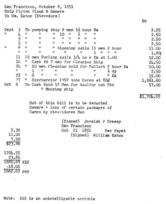
Figure 14 – Record of Stevedore Service for Flying Cloud while in San Francisco 35
Figure 15 - Captain Josiah Perkins Cressy.......................................................... 36
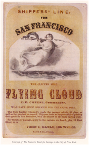
Figure 16 – Sailing Card of the Flying
Cloud....................................................... 37
Figure 17 - Code Flags for Flying
Cloud - 2636................................................... 38
Figure 18 - "Scientific
American" article - February 13, 1858........................... 39
Figure 19 - Captain Alexander Winsor................................................................ 40
Figure 20 - Map of the World................................................................................... 46
Figure 21 - "Key locked scarf".................................................................................. 58
Figure 22 - "Key locked scarf" Chariot of Fame & Great
Republic.................... 58
Figure 23 - Flying Cloud keel
scarfs........................................................................ 59
Figure 24 - Rabbet....................................................................................................... 61
Figure 25 - Keelson Arrangements........................................................................ 62
Figure 26 - A Clinch Ring......................................................................................... 64
Figure 27 - Keelson Fastening Arrangement...................................................... 65
Figure 28 - Molding of midship frame - Champion
of the Seas....................... 70
Figure 29 - Molding of midship frame - Charriot
of Fame............................... 71
Figure 30 - Molding of midship frame - Great
Republic.................................. 71
Figure 31 - Molding of midship frame- Flying
Cloud....................................... 71
Figure 32 - Dimensions of Garboards and Thick Bottom Planking............ 81
Figure 33 - Planksheer and Rail Molding............................................................ 86
Figure 34 - Topgallant Forecasstle....................................................................... 118
Figure 35 - Topgallant Water Closets................................................................. 119
Figure 36 - Galley Range........................................................................................ 121
Figure 37 - Cross Section of Poop Deck Cabin................................................. 123
Figure 38 - Deck Cabin............................................................................................ 123
Figure 39 - Aft Cabins.............................................................................................. 124
Figure 40 - Forward Cabin..................................................................................... 125
Figure 41 - State Room Arrangements............................................................... 128
Figure 42 - Flying Cloud After
Cabins................................................................. 128
Figure 43 - Stag Hound After
Cabin...................................................................... 130
Figure 44 - Rudder.................................................................................................... 131
Figure 45 - Principal Dimensions of Launches & Cutters............................ 135
Figure 46 - Lines of a 28 foot Cutter..................................................................... 135
Figure 47 - Sail Plan of 28 Foot Cutter................................................................ 136
Figure 48 - Sail Plan of 30 Foot Launch............................................................. 137
Figure 49 - Lines of 30 Foot Launch.................................................................... 137
Figure 50 - Size of Anchors for Launches and Cutters.................................. 138
Figure 51 - Weight of Anchors.............................................................................. 139
Figure 52 - Chain Size vs Anchor Weight......................................................... 140
Figure 53 - Fluke of Common Anchor................................................................ 141
Figure 54 - Anchors.................................................................................................. 142
Figure 55 - Fly Wheel Pump.................................................................................. 145
Figure 56 - Windless................................................................................................ 146
Figure 57 - Scuppers................................................................................................ 149
Figure 58 - Water Tank Foundation.................................................................... 156
Figure 59 - Probable Nail Arrangement in Yellow Metal Sheathing........ 159
Figure 60 - Sheathing Mallet and Punch........................................................... 160
Figure 61 - Fife Rail.................................................................................................. 170
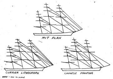
Figure 62 - Stay Arrangement............................................................................... 178
Figure 63 - Shroud Diameter vs Deadeye Diameter....................................... 180
Figure 64 - Bowsprit Rigging................................................................................ 181
Figure 65 - Patent Truss.......................................................................................... 182
Figure 66 - Bulwark Fairlead................................................................................. 186
Figure 67 - Flags of the Flying
Cloud.................................................................... 188
Figure 68 - Position of Reef Points....................................................................... 193
Figure 69 - Construction of Jibs............................................................................ 195
List of Tables
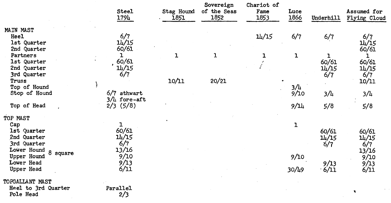
Table 1 - Paintings, Pictures, Models, Plans, and logs
of the Flying Cloud 43
Table 2 - Ships Described in the Boston Daily Atlas........................................ 49
Table 3 - Table of Offsets........................................................................................... 55
Table 4 - Comparison of keels of McKay ships.................................................. 56
Table 5 - Lengths of Keel Scarfs.............................................................................. 59
Table 6 - Floor Timber Molding.............................................................................. 69
Table 7 - Size of "top timbers".................................................................................. 74
Table 8 - Dimensions of garboards........................................................................ 78
Table 9 - Mortise Arrangement............................................................................... 96
Table 10 – Knee Materials...................................................................................... 107
Table 11 - Hanging Knees - Size and Fastening.............................................. 108
Table 12 - Dimensions of Hold Stanchion........................................................ 110
Table 13 - Size of Between Deck Stanchions..................................................... 111
Table 14 - Deck House Accommodations......................................................... 121
Table 15 – Stateroom Passenger Accommodations....................................... 126
Table 16 - Lloyds Regulation for Ground Tackle............................................ 139
Table 17 - Capstan Material.................................................................................. 143
Table 18 - Number of Water Tanks and their Capacity................................ 155
Table 19 - Sheathing Requirements.................................................................... 159
Table 20- Number of Sheathing Nails per Pound.......................................... 160
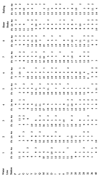
Table 21 Dimensions of Masts and Yards........................................................ 165
Table 22 Taper of Masts......................................................................................... 167
Table 23 - Size of Top Stanchions for a Ship of the Line............................... 169
Table 24 - Diameter of Yards................................................................................. 170
Table 25 - Bowsprit Diameters............................................................................. 171
Table 26 - Jib-Boom Diameters............................................................................. 172
Table 27 - Dolphin Striker Diameters................................................................. 172
Table 28 - Whisker Boom Diameters.................................................................. 173
Table 29 - Spanker Boom Diameters................................................................... 173
Table 30 - Gaff Diameters....................................................................................... 174
Table 31 - Important Spar Dimensions of the Flying Cloud....................... 175
Table 32 Size of Standing
Rigging...................................................................... 177
Table 33 - Location of Shrouds............................................................................. 179
Table 34 - Size of Chain for a Ship of 1000 Tones........................................... 185
Table 35 - Position of Reef Points......................................................................... 191
Table 36 - Sail Dimensions.................................................................................... 191
Table 37 - Location of Spanker Reefs (Ft)........................................................... 196
Table 38 - Sail Construction Details.................................................................... 198
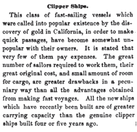
Although there have
been several very successful attempts at presenting the history of the clipper
ship era, most outstanding of which are Fairburn's "Merchant Sail" and Cutler's "Greyhounds of the Sea", it seems that no one has sought to
compile the material facets of the ships which made the era, i.e. how a clipper
ship was constructed. It was first thought that ships of the entire era could
be considered, but shortly after commencing the investigation it was decided
that an evaluation of this magnitude would be unwieldy, and it became apparent
that only a single ship could be considered in detail.
The two outstanding
builders of the time were William H. Webb of New York and Donald McKay of
Boston. The choice between these two was one of expediency rather than any
decision of relative stature. Much of the information required in a study such
as this is local, and the time required to discover much of it necessitates
being in close proximity to the source for an extended length of time. Living
in Boston at the time it was therefore most expedient to be concerned with
Donald McKay and his ships.
As the Flying Cloud is probably McKay's most
famous ship, she was chosen as the most appropriate to investigate. In looking
for the details of the Flying Cloud
it was discovered that no one had compiled the known facts concerning this
ship, or for that matter, any clipper ship. The author does not pretend to know
anything about the Flying Cloud that
others do not; however, this paper does attempt to assemble the known facts and
presents reasonable assumptions where, the facts are unavailable. The paper has
been completely referenced, not for the ease of reading (which is undoubtedly
hindered) but so that the sources may be evaluated by those interested in so
doing. Virtually every informative publication consulted has been listed in the
Bibliography.
The plan of this book
is to first present a short history of the era in order to provide the
background and setting of the building of this ship. Section II is a biography
of Donald McKay which gives a picture of the man who was responsible for the Flying Cloud, while the third- section
is a history of the Flying Cloud. The fourth section is a detailed
description of' the Flying Cloud; how
she was built, what materials were used, what accommodations were provided, her
rigging, sails, etc. This section has been the object of most of the time spent
in this study since it is the subject generally not covered by others. The last sections present miscellaneous
model information and large scale plans (½" = 1') of the Flying Cloud.
In doing any type of
historical literature survey it is necessary to weigh the evidence gathered
from different sources against the reputation and supposed knowledge of the
author. Thus a reconstruction is based on what is believed to be the most
reliable sources, filling in the unknowns as best as is possible. This method
undoubtedly results in many inaccuracies, but the author knows of none better.
It is an odd quirk of
societies that certain eras of history are disregarded until all of the people
who lived at the time have passed on. Perhaps it is the fear of being
contradicted by someone who "was there" and knows what happened; perhaps,
as, long as people can remember an era there is no compulsion to write it down.
Regardless of the cause, the effect is equally unsatisfactory. If this paper
helps anyone in the future to trace this era a little better, then it has
served its purpose.
Of the large number of
accounts of merchant shipping during the period 1850 to 1860, William
Fairburn's monumental six-volume work "Merchant
Sail" is by far the most scholarly work. Cutler's "Greyhounds of the Sea" is excellent
account, while Clark's "The Clipper
Ship Era" has long been looked upon as the classic light account of
the period. Since there are such excellent accounts of this period we feel it
unnecessary to summarize them in more than a cursory manner
According to Robinson
and Dow, the word "clipper" as applied to a fast vessel is supposed
to have originated in the Pennsylvania-German word "klepper" meaning
a fast horse. There is some question as to the actual dates of the clipper ship
era, but it is evident that the extreme clipper ship was an economic success
only between the years 1850 through 1854. Ships were built on clipper lines
before 1850, and clippers were sailed after I854, but we have taken the word
"era" to mean the period during which this certain type of ship was
optimum for the existing conditions.
Although the so-called
Baltimore clippers had been constructed for some time, these vessels were not
ships in the strict sense of the word since they were often schooners and never
had more than two masts. However, they were the forerunner of the future
clippers, particularly in the form of the bow. The first ship of clipper form is generally regarded to be
the Rainbow, a 750-ton vessel launched by Smith & Dimon of New York, in
1845. John Willis Griffiths designed this ship, and he can justifiably be
called the originator of the clipper ship form.
For any change, there
must be a cause and the clipper ship era came to America because gold was
discovered in California. With the overwhelming demand for transporting people
and goods to San Francisco, fast ships were a necessity. With inflationary gold
dust in abundance, freight rates rose so high that the capacity of a ship
became minor in importance; speed commanding the premium. Thus high speed, low
capacity, ships like the Flying Cloud
were built which, in any other period, would have been folly.
Because of the expense
of operating these low tonnage Vessels, the first slight quiver in the economy
relegated the extreme clipper to a historical rather than contemporary
position. This quiver came with the slight recession of I854, which saw New
York to San Francisco freight rates fall to one half their previous value.
Although the events of I854 signaled the finish of the extreme clipper, it took
the general depression of 1856-7 to end the extreme clipper era, with the
medium clipper, a high capacity ship with fuller lines than the extreme
clipper, taking its place.
The clipper era was
outstanding in sailing history; it was a romantic period which will live on and
be remembered for the sailing records that were set. Although much must be said
for the shape of the clipper in setting these records, it was Lieutenant
Matthew Fontaine Maury, U.S.N., a celebrated hydrographer, who made many of
these records accomplished facts. He believed that it' was possible to make
current and weather charts which ships could follow to reduce sailing times. He
asked every ship's captain to fill in reports concerning the strength and
direction of the wind and water currents, the temperature of the air and water,
and any unusual weather which was observed. He compiled these into a
four-volume work entitled "Sailing Directions", which if followed
enabled days and sometimes weeks to be cut off the Cape Horn voyage.
With this brief
outline we will leave a subject better covered else where, but this should
provide some background for the following sections and should explain some of
the events to be mentioned in Section IV.
Figure 1 - Matthew Fontaine Maury
Although
not of primary importance to this study, a biographical sketch of Donald McKay
has been included for the sake of completeness. Richard C. McKay has given us an excellent
biography of his grandfather in "Some
Famous Sailing Ships and their Builder Donald McKay" and much of the
material presented in this paper has been drawn from his book. An even better
source from which to obtain an insight into the true significance and
accomplishments of the men of the clipper ship period is "Merchant Sail" which we have drawn
upon heavily. This work evaluates the men and their deeds rather than being
simply biographical.
Donald
McKay was born in Shelburne, Nova Scotia, on September 4, 1810, His most famous
ancestor, another Donald McKay, died at Tain, Ross County, Scotland, in 1395.
His grandfather, also named Donald, was a British Army officer who emigrated to
Nova Scotia after the close of the American Revolution, and his father, Hugh
McKay, raised a family of seven sons and a number of daughters here. In 1826,
when 16, Donald McKay traveled to New York, then the leading shipbuilding
center of the United States, where he found employment as a day laborer in
Isaac Webb's yard located along the East River between 5th and 7th Streets. On
the 2lth day of March, 1827, Donald became "indentured" to Isaac Webb
for a term of four years, six months, and eleven days, at a wage of $2.50 per
week plus $40 per year. At the age of 21, Donald McKay had finished his
apprenticeship; but by modern standards his wages were little indication of his
increasing social status; at work 15 hours a day, he had one hour for breakfast
and two hours for lunch for $1.25 a day. Webb agreed to release Donald before
his indenture time was complete, whereupon he joined the firm of Brown &
Bell of New York. In 1832, while still in the employ of Brown & Bell, McKay
married Albenia Martha Boole, daughter of another East River shipbuilder, and
on February 1, 1834, their first child, Cornelius Whitworth McKay was born.
McKay's next job was with the Brooklyn Navy Yard at the suggestion of his
friend Jacob Bell, but strong native American feelings prevalent at the time
forced him to look elsewhere.
Mr. Jacob
Pell then sent McKay to Wiscasset, Maine, to superintend the building of some
ships for New York houses. While visiting Newburyport, he finished the U21 ton
ship Delia Walker for John Currier, Jr., and it was here that McKay met the
owner of this vessel, Dennis Condry, who was to play an important role in
McKay's future.
In l84l
McKay entered into partnership with William Currier, forming' the firm of
Currier & McKay in Newburyport, Massachusetts, and moved his family from
New York. However, after building three vessels the partnership was dissolved,
models and moulds being divided with a saw. Next McKay joined with William
Pickett, of Newburyport, to form the firm of McKay & Pickett. This firm built the packet ships St.
George and John R. Skiddy during 1843-44. Upon the recommendation of Dennis
Condry, Enoch Train, at the time leading shipping merchant of Boston, visited McKay
and contracted for the 620 ton ship Joshua Bates, pioneer ship of Train's
Liverpool line. The ship was completed during 1844, and at Train's request, and
with his financial help (which McKay continued to receive off and on), Donald
McKay, now age 34, moved to East Boston where he opened his own shipyard at the
foot of Border Street. His first ship, the Washington Irving was launched on
September 15, 1845. This yard produced ships until 1852.
After
McKay became settled in East Boston, he brought his relatives around him to
share his prosperity.
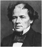
Figure 2 - Donald McKay at the age of 20
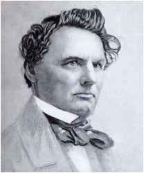
Figure 3 - Donald McKay at the age of 54
As far
as these relatives are concerned, we have information on only four of his
brothers and none of his sisters. Duncan McLean, in his description of the ship
Barreda Brothers, mentions the fact that all seven of the "brothers
McKay" were shipbuilders. Laughlin McKay, who had learned the shipbuilding
trade also under Isaac Webb, was to be come known not as a shipbuilder, but as
the captain of the clipper Sovereign of
the Seas. Simon McKay is known BDA to have built the 350 ton
ship Wildfire in 1853 and Hugh McKay
built BDA the 750 ton ship Parreda brothers in l85h. The fourth and
youngest brother was Nathaniel who evidently at some later time joined Donald
in the last Boston shipyard and managed many of its affairs during the later
years.
McKay as
well as producing some of the most famous sailing vessels the world has known,
devised new ways of "doing" things.1 He developed a saw which could
be tilted while sawing, thereby enabling him to cut complicated twists and
turns in a fraction of the time it would take to hew the timber by hand. His
also was the first yard to use a crane rather than manpower to lift timbers
into place.
In
December, 1848, Donald's wife Albenia died after a brief illness.
Late in
1851 the city authorities notified McKay that the land at the foot of Rutaw
StreetB113 occupied by his shipyard was to be taken over for an
extension of Border Street, so he established himself a short distance north of
the former yard on Border Street between Monmouth and White Streets (Figure 4A).
Figure 4A - Maps of East Boston 1851, 1856
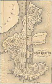
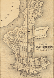
1851 1856
In July
1852, the Sovereign of the Seas, the
first product of this new yard was launched.
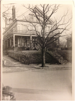
It was
customary after the launching of a ship that McKay's friends would return to
his house at 80 White Street in the Eagle Hall section of East Boston to
celebrate the event. Although he had first lived on Princeton Street, he later
moved to White Street and continued residence there until retirement. A picture
of this house as it looked in 1928 is presented below.
Figure
4B Donald McKay’s house at
80 White Street in East Boston
It was
with the Sovereign of the Seas that
McKay entered mercantile as well as mechanic affairs. This ship, costing an
estimated $95,000 was built with his own money, and for her first voyage he
placed in command his brother Laughlin.
In June
of 1853, Donald and his second wife, Mary Cressy Litchfield of East Boston,
sailed aboard the Sovereign of the Seas
for Liverpool. It was this wife who has been given credit as the originator of
many of the names to McKay's ships.
During
1853 McKay was completing for his own account what he considered to be his
greatest masterpiece‚ The Great Republic.
This 4555 ton ship was launched October 4, 1853, and sent to New York. However,
the ship was burned after being loaded, and being underinsured, McKay was
almost ruined.
We have
already seen that in 1854 there ceased to be a necessity for ships of great
speed. The surplus of ships and the business depression which followed the
California inflation saw New York to San Francisco freight rates drop to
one-half, causing many ships to lay idle, while there was little incentive to
build new ones. To aggravate the situation steamers began to offer serious
competition to packets. James Baines, however, kept McKay going by ordering a
number of ships for his Australian Black Ball Line. According to an article in
the Boston Daily Atlas of December 18, l854, Baines paid about $80 per
registered ton for these ships.
In 1854
Donald McKay made a determined effort to meet the decline in California trade
by establishing his own line of European packets. How ever, only two ships, the
Commodore Perry and the Great Tasmania (later known as the Japan) were put into this service and
these were soon sold abroad. In February, 1855, McKay again went abroad in one
of his ships, this time in the Donald
McKay. However, for all his effort, in the autumn of 1856, McKay failed,
along with many other Boston businessmen. Since sale of his assets would not
have benefitted his creditors greatly, he was allowed to keep the yard. But
from the end of 1856 through 1857 the yard lay idle, as did most of the ships
already on the sea. Sometime in 1858, work was begun on the 1,097 ton ship Alhambra, remaining on the stocks over a
year. This is significant when contrasted with the building of the Stag Hound, which reportedly required
sixty days. During the next two years, McKay and his son, Cornelius, turned out
only four schooners for Cape Cod fishermen.
This
brings us to the Civil War and McKay's yard began to turn out monitors, iron clad
gunboats, and various other craft. Since there was an unpredictable evolution
of ship construction with the introduction of these "iron clads",
contracts were written to provide for any changes necessitated by altered
methods of warfare. However, reimbursement for the added expenses got mixed up
in politics and it was not until long after McKay was dead that his claim was
settled. Francis B. C. Bradlee, in his booklet, "The Ship Great Republic and Donald McKay, Her Builder",
discusses McKay's efforts after the war to build iron ships, marine engines,
and railroad locomotives, the business being carried on under the name of McKay
& Aldus.
McKay
made one last bid for the clipper ship when he built the Glory of the Seas in 1869 for his own account. It is known that
this under taking hurt him financially, and it is partly because of this that
in the same year the firm of McKay and Aldus sold out to the Atlantic
Works. However, the launching of
the Glory of the Seas has given us
the only photograph yet discovered of McKay's shipyard. Mr. McKay is standing
in the foreground, but unfortunately is back-to. At this time it was Nathaniel
McKay who was the leading spirit of the firm. The yard must have been at least
partly dismantled for we are told that the saw mentioned earlier was sold to a
shipyard in Bath, Maine. There are, how ever, still records of McKay ships
built after this time so that evidently McKay continued to work even though he
no longer owned the yard. In l875 the McKay yard constructed the sloop o' War Essex, and the last job of the McKay
yard was to repair the yacht America
for General Benjamin F. Butler. Work on this ship was completed about June 15,
1875, providing a fitting end for this yard. It was in 1851, the year McKay
became so famous as the builder of the Flying
Cloud, that the America won a
contest which was noted around the world‚ the first America Cup Race. Donald
McKay retired to Hamilton, Massachusetts, where he died September 20, 1880. He
lies buried in Oak Hill Cemetery in Newburyport, Massachusetts. We are toldT288
that McKay's second yard on Border Street was afterwards the site occupied by
George McQuesten & Co., hard pine lumber dealers.
Although
McKay was not a technical man, and found no new principal or theory of ship
design (rather following Pook, Griffiths, and Webb), he did have an excellent
feeling for the form of a ship. Boston and New York, as the two foremost
shipbuilding centers of the 1850's, had considerable competitive feeling toward
each other. McKay was adopted by Boston and his ships were publicized at the
expense of those of the other Massachusetts builders, even though some of these
builders are now considered to have produced better ships. Outstanding among
those who whom history has slighted is Samuel Pook whose Red Jacket is considered by some to be the best clipper ship ever
produced. New York acknowledged many builders of clipper ships, considering
William H. Webb as outstanding, but adopted no one. Thus, we see why McKay is
better known than other builders of clipper ships, and many say unjustly so,
for he produced fast vessels but generally did not create ships that could make
money in competitive trade under ordinary commercial conditions. The
outstanding example of this was the Great
Republic, which drew so much water it could have entered very few ports.
McKay was a product of an age -- but an age so short lived hat he was lifted to
its heights and broken by it, all in the course of only four years.
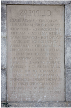
To
commemorate this man, and the ships he built, a group of interested persons
decided to erect a suitable monument. The 52-foot granite monument was erected
in 1933 on the north side of Castle Island where it stands today (1958). The
following pictures show the setting of this monument and the inscriptions on
each side.
Figure 5 - Front (North East) side of monument
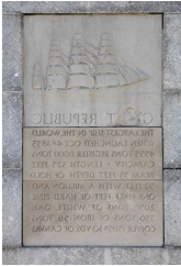
Figure 6 - Back (South West) side of monument
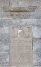
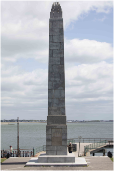
Figure 8 - Left (North West) side of monument
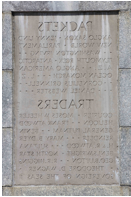
Figure 9 - Right (South East) side of the monument
The
history of the Flying Cloud is
perhaps not a necessary part of this study. However, what is included here is
more than just history; it is the personality of a ship. Subsequent to the
record making runs of McKay's Flying
Cloud, the name became world famous, and was even the name of an early
automobile. Although no attempt was made to discover all of the American
vessels named Flying Cloud, six were
found. In 1851 there was a 21 ton schooner built at Machiasport, Maine; in 1852
a 109 ton schooner/built at Bristol, Maine; also in 1852 a 350 ton bark was built
in Williamsburg, New York; in 1851, a 190 ton brig built in Brewer, Maine; and
in 1859 a 222 ton brig built in Biddeford, Maine; all were christened the
"Flying Cloud". There was
also a sloop named the Flying Cloud
which was among the ships that tested the blockade of the Gulf ports during
1861-1865.
The
following history has been compiled from many books; primarily from Fairburn,
Howe & Matthews, McKay, American
Neptune,' and the papers of S. Griffitts Morgan, the supercargo for
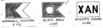
Grinnell, Minturn & Co. in San Francisco whose papers are in the Harvard
Business School. These papers evidently include all the crew advances, bills,
bills of lading, invoices, freight lists, letters, etc. concerning the ship
while in San Francisco.
The
only appropriate starting point for a history of the Flying Cloud is with the man who first conceived the ship, George
Francis Train, Jr., partner in Enoch Train & Co. In his biography he tells
us of the early history of this ship in the following way.
When the gold fever was
getting the country frantic, and everyone apparently wanted to go to
California, I said to McKay, "I want a big ship, one that will be larger
than the Ocean Monarch." McKay
replied, "Two hundred tons bigger?" "No", said I, "I
want a ship of 2000 tons." McKay was one of those men who merely ask what
is needed. He said he would build the sort of ship I wanted. "I shall call
her the Flying Cloud", I said.
The
half-model of the Flying Cloud is no
longer in existence. When Donald McKay retired, his models were moved from the
East Boston yard and stored in his barn. It was after McKay's death in 1880
that his eldest son, Cornelius, discovered that, with the exception of the Stag Hound, all of the models had been
used as firewood during a shortage of coal. Richard McKay claims that in 1869
Donald gave the model of the Great
Republic to his daughter then living in Saxony. In 1928 Richard McKay had
the only other original McKay model known to exist‚ the Glory of the Seas. Attempts to locate Richard McKay, last known to
reside in Brooklyn, New York, have failed.
The
construction of clipper ships was evidently of considerable interest to Henry
Wadsworth Longfellow, and George Train claimed that Longfellow's poem‚ "The Building of the Ship"‚ was
written in 1850 to commemorate the construction of the Flying Cloud, then on the stocks.
Although
George Train desired a 2000 ton ship, when the Flying Cloud was designed she measured only 1782½ tons (most
often recorded as 1782 but sometimes 1783).
While
still on the stocks, Enoch Train & Co. sold the Flying Cloud to Grinnell, Minturn & Co. of New York. Details of
this transaction are given by George Train.
Not only shipbuilders
but the whole world was talking of the Flying
Cloud. Her appearance in the world of commerce was a great historic event.
No sooner was the Flying Cloud built
than many shipowners wanted to buy her; among others the house of Grinnell,
Minturn & Co. of the Swallow-Tail Line of Liverpool asked what we would
take for her. I replied that I wanted $90,000 which meant a handsome profit.
The answer came back immediately‚ "We will take her." We sent the
vessel to New York under Captain Creesy while I went on by railway. There I
closed the sale, and the proudest moment of my life, up to that time, was when
I received a check from Moses H. Grinnell, the New York head of the house, for
$90,000.
McKay238
reports that the Flying Cloud cost
$50,000. The ship was launched April 15, 1851, the event being mentioned in the
April 16 issues of the Boston Daily Atlas
and the Boston Semi-Weekly Atlas.
This undoubtedly much publicized event was also recorded in a woodcut (Figure 10).
Figure 10 - Launch of the Flying Cloud, April 15th, 1851
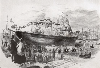
The
ship was sent in tow of the tug Ajax to New York under command of Captain
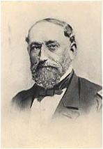
Josiah Perkins Creesy37, having been born in Marblehead, Mass. in
l814. Arriving April 28, it was turned over to Grinnell, Minturn & Co., to
sail under their California line house flag where she remained for six years.
McKay144
claims that Train & Co. had appointed Captain Creesy to command the Flying Cloud, but as he also enjoyed a
high reputation in Now York, he was retained by Grinnell, Minturn & Co. The
ship was insured with the Atlantic Mutual Insurance Co. of New York, holding an
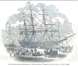
Al rating for her first four voyages. She was loaded at Pier 20, East River
(See Figure 11). Figure 12 is a reproduction of a picture presented by McKay.
Figure 11 - Map of East River Waterfront, New York
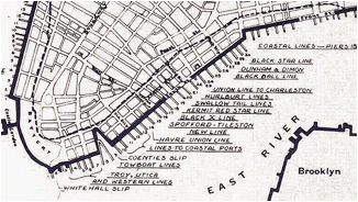
Figure 12 - Loading of the Flying Cloud
The
morning edition of the New York Herald of May 10, 1851, carried following
story:
NEW CUPPER SHIP FLYING
CLOUD‚ This beautiful specimen of naval architecture is now receiving her
freight at the foot of Maiden Lane, preparatory to her departure on the 24th
inst. for California and China. She is owned by Messrs. Grinnell, Minturn &
Co., who also own the Sea Serpent, to
which she in some respects bears a lone resemblance. The Flying Cloud is a very sharp vessel, and bids fair to take as good
a voyage as any of her predecessors. She registers 1,782 tons, and is
constructed mostly of white oak, and is copper-fastened throughout. She was built at East Boston, by Mr.
Donald McKay.
The New
York Commercial Advertiser of May 9, 1851, also carried a description of the Flying Cloud but it was essentially a
copy of the Boston Daily Atlas report of April 25, 1851, given in Figure 13.
The Flying Cloud sailed from New York June
2, 1851, on her first voyage to San Francisco. This ship excelled in whole sail
breezes (admittedly it was often bettered in light airs), and arrived in San
Francisco August 31, 89 days and 21 hours from New York (anchor to anchor), a
new record for the run. The abstract log of this voyage is reproduced in the
Appendix. Once in San Francisco, most of the crew left for the gold fields,
requiring that the voyage to China be made with only one steward, one ordinary
seaman, and 18 seamen. The mate, who had been suspended from duty for cutting
up rigging made plans to bring a suit against Creesy for damages. It might be
of interest to include here a receipt for the various stevedore services
rendered while in port. We also know that at this time the ship was painted
outside by Lilly & Davis for a "fee of $90.00" (See Figure l4).
The Flying Cloud left San Francisco
October 20th, arriving in Hong Kong December 5, 1851.
It was
on the return trip from Whampoa (Hong Kong) (sailed January 6, 1852) to New
York that Captain Creesy had the rare opportunity of reading his own obituary.
In exchanging food for New York newspapers with a ship outward bound, he found
reports that he had died on the second day out of San Francisco. This
announcement was advantageous inasmuch as it induced his late mate's sea lawyer
to drop his proceedings. It was said later that this was an intentional rumor
started by Creesy‚ probably a very valid assumption. McKay151 says that Grinnell, Minturn & Co.
had the log of this voyage printed in gold upon white silk for distribution
among their friends, although none of these was discovered during this study.
When in New York, at Captain Creesy's insistence, the Flying Cloud's fore and main masts and spars were replaced, the
yards on the foremast being made the same dimensions as those on the main,
thereby increasing her sail area slightly. She was also fitted with new
rigging.
The
second voyage of the Flying Cloud began
May 14, 1852, under the command of Captain Creesy; she arrived in San Francisco
September 10th. It was on the first leg of this trip that the N. B. Palmer, under Captain Charles P.
Low, having left New York eight days after Creesy, caught up with the Flying Cloud being 40 days out. Creesy
was extremely impolite to Low but the truth is Crersy depended more on his luck
than he did on Maury's sailing directions and often went off the recommended
track searching for wind. However, Low had a mutinous crew and subsequent to
the meeting was forced to put into Valparaiso, arriving in San Francisco a full
three weeks behind Creesy. On
April 28, 1853, the Flying Cloud left
New York on her third voyage, again under Captain Creesy. It was on this
occasion that the Flying Cloud was
beaten by the Hornet. The vessels
were in company off Sandy Hook, the Flying
Cloud was seven days ahead at the Horn, but Creesy again discarded Maury's
sailing directions on the latter part of this voyage and arrived in San
Francisco only to see the Hornet at anchor. He was so aware of his misjudgment
that he refused to turn over his complete log to Lieutenant Maury. Thus only the run from New York to the
Atlantic equator, where he knew he had soundly beaten the Hornet is available today. Creesy was not a humble man.
|
|
Figure 13 - Boston Daily Atlas
Report of the New Clipper Ship Flying
Cloud
|
|

The New Clipper Ship Flying Cloud,
of New York.
The plan of this section is to take each major timber
assembly in the ship and treat it in detail. In general (but not in some
particulars) we have presented this in the same order that, the ship would have
been constructed.
Material The Boston Daily
Atlas (hereafter referred to as BDA) reports that the keel is of rock maple.
Size The BDA states that
there are three depths of keels, molding a total of 44 inches, and siding 16
inches. Neither the MIT or Hall lines of the Flying Cloud show a keel of 44 inches, showing 27 and 32 inches
respectively It is possible that ships draughts were drawn without showing the
shoe or false keel, since this type of keel was attached after construction of
the ship was well along. Both Griffiths136 and Peakel2
suggest a maximum thickness of 6 inches for a false keel, although Peake110
does make note of a 10 inch shoe.
If it is assumed that a 6 inch false Keel was attached, but not shown on
the plans, there remain discrepancies of 11 inches in the MIT plan and 6 inches
in the Hall plan. It can only be assumed that the draughts are probably
inaccurate—a fact which has been mentioned elsewhere (see Part V).
Table 4 has been compiled from data
given in the BDA reports of various McKay built ships. The data as reported
(first two columns) does not exhibit any definite trend; however, if a 6 inch
shoe is assumed to be the third depth on those ships which have three depths of
keel, then a trend is in evidence.
As partial support for this assumption, it is known that both the Stag Hound BDA and Champion of the SeasH87 had 6
inch false keels, while the Great
Republic had one of 4 ½ inchesS11. Based on this table,
it has been assumed that the keel was composed of a 6 inch shoe and two 10 inch
depths.
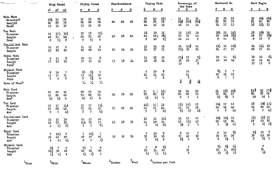
Table 4 - Comparison of keels of McKay ships
Total
Number
Average Average
depth
of depths molding molding
of
per
depth two depths
with
6” shoe
Stag Hound 46” 3 15.33” 20”
Flying Cloud 44 3 14.67 19
Staffordshire 38 2 19.00 19
Flying Fish 38 3 12.67 16
Sovereign of the Seas - - - -
Westward Ho 30 2 15.00 15
Bald Eagle 30 2 15.00 15
Length The Chariot of Fame plan shows keel timbers
27 to 47 feet long averaging 40 feet; the piece of the keel of the Champion of the SeasH87
averaged a little more than 47 feet, while the Great Republic plan shows 50-52 feet. It is reasonable to assume
the same size timbers were available for the Flying Cloud; thus the length of keel timbers has been assumed as
45 feet.
Taper Although some
authorities seem to favor the tapering of the keel at one or both extremities,
there was equal justification foundG13° in the literature for assuming a
constant siding. No taper is indicated on either the Hall or MIT plans, nor was
a taper indicated in very many of the BDA reports. Therefore, no taper has been
assumed in the Flying Cloud.
Scarfs According to
Griffiths136, a hooked scarf was the type usually preferred for
keels; Peake10 states that a tabled scarf was used; while Curtis29
gives four types of scarfs—plain, hooked, key locked, and key locked
hook—but seems to favor the plain type. Fincham8 states that
horizontal scarfs were usual, double the room and space in length which allowed
two bolts in each (lip of the scarf) through the floors and keelson. This is
the same length specified for the keelson scarfs. Wilson185 states that horizontal plain scarfs,
four frames in length were usual, with the nibs coming between two frames. The Chariot of Fame plan shows key locked-scarfs.
The BDA in several cases made mention of the types of scarfs used for the keel:
The Empress of the Seas had square
keyed scarfs, the Dauntless had lock
scarfs, the Winfield Scott had locked
scarfs, and the Champion of the Seas
had keyed scarfs. Curtis29 shows a "key locked scarf"
which appears to be the same as shown on the Chariot of Fame plan. Curtis gives the following proportions for
this type scarf.
Figure 21 - "Key locked scarf"
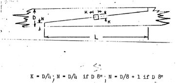
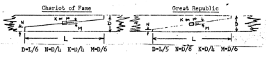
The Chariot of Fame plan shows the fallowing proportions for her keel
and keelson scarfs, and the keel scarfs shown on the Great Republic plan.
Figure 22 - "Key locked scarf" Chariot of Fame & Great Republic
Griffiths135 implies
that keel scarf nibs are commonly at least six inches, and, in the case of the Flying Cloud (with 7 inch garboards), 7
inches would be expected. However, he recommends a 3 inch scarf nib as being
sufficient. Curtis30 gives the rule that a nib should be one-eighth
the molded dimension plus 1 inch, or 3 ⅜
inches for a 19 inch depth. Since
there is no specific mention in the BDA reports of any other type of scarf
used, it has been assumed that the "key locked scarf" was the one
most used and this type has been accepted for the keel of the Flying Cloud. The proportions are shown in Figure 23.
Figure 23 - Flying
Cloud keel scarfs
Table 5 gives the lengths of scarfs
reported in the BDA and other reports of various ships. They are listed in
order of launching date.
Table 5 - Lengths of Keel Scarfs
Ship Length
of Scarf (ft)
John Bertram (1) 8
Winfield Scott (1) 9
Stag Hound (l,M) 8-10
Dauntless (1) 10
Flying Cloud M) -
Westward Ho (l,M) 12
Empress of the Sea (1,M) 10
Water Witch (1) 12
Great Republic (2,M) 12
Eagle Wing (1) 12
Lightning (1,H) 12
Champion of the Seas (l,M) 12
(1) BDA (2) Hall (M) Built by
McKay
The molding and siding of the keels
of these ships varies little, and any difference is not generally reflected in
the length of the scarf. Thus, it is obvious that the rule outlined above was
not adhered to. Although, there is evident a trend towards longer keel scarfs
in later ships, because of the similarity between the Flying Cloud and Stag Hound
in other respects, a scarf length of 10 feet has been assumed which would span
three frames. Table 5
substantiates this conclusion to a degree since another McKay ship built after
the Flying Cloud (the Empress of the Seas) had 10 foot keel
scarfs; no attempt is made to explain why the Western Ho had 12 foot scarfs.
Fastening Wilson185 states that keel
scarfs are bolted with two copper bolts through each nib and four additional
ones through each scarf, all clinched on composition plates. Fincham9
says scarfs are bolted with eight bolts, driven with a ring upon the head and
clinched over a ring. The only two statements concerning keel fastening
concerning specific ships were found in the BDA report of the Dauntless and in Hall's87
report of the Champion of the Seas.
The only statement the BDA makes concerning the Flying Cloud is that her keel and keel scarfs are fastened with
copper. Hall's87 description of the Champion of the Seas states that scarfs 12 feet long were fastened
with ten 1-inch copper bolts and although scarfs 10 feet long have been assumed,
they would still be fastened with ten 1-inch copper bolts, notwithstanding the
fact that the BDA reports the Champion of
the Seas was fastened with 1¾ inch bolts in her keelson, which does
not agree with the statement made by Hall. The DauntlessBDA had the parts of her keel bolted every 4
feet with 1⅛
inch copper bolts while 1¼ inch bolts were used in her keelson
fastening; the John Bertram had both
her keel and keelson fastened with 1¼ inch copper.
The Chariot of Fame plan shows the fastening arrangement used on one of
its keel and this arrangement has been accepted as valid for the keel scarfs of
the Flying Cloud. It has been assumed that the keels were
fastened with 1⅛ inch copper bolts every 4 feet while the keel
scarfs were fastened with 1 inch copper bolts, all riveted over rings.
Curtis30 says the wedges
(keys) of the scarf are made of hard wood, have a taper of about ½ inch
to the foot, and should be driven simultaneously from each side and should be
wedged at the small ends. This description of the wedges has been adopted.
Sag Several authorities
remarked that the keel should be laid with a sag in the middle which would
straighten when the ship hogged after being launched. Curtis3
suggests a sag of 1½ to 2 inches per 100 feet, evenly distributed over
the entire length; Griffiths merely suggests "several" inches, but
recommends that the forward end be raised higher than aft. Griffiths58
would seem to have a logical argument inasmuch as the bow has less buoyancy and
therefore would hog to a greater degree than the stern. His "several" inches could
easily have been 3 or 4, or the amount suggested by Curtis since the keel is
about 200 feet long. Although there is only the justification given above for
doing so, it has been assumed that the bow of the Flying Cloud was raised 2½ inches and her stern 1½
inches above the keel at the dead-flat frame. The only time the BDA made
mention of a sag in a ship's keel was in the case of the 350 ton clipper barque
Wildfire which had her "keel (a little over 100 feet) raided a foot from a
straight line forward”
Rabbet Fincham9
states that the rabbet is taken out as a equilateral triangle, all sides equal
to the thickness of the garboard.
The Chariot of Fame and Great Republic plans show a notched
rabbet, with keel sided normally for the upper half of the rabbet; the lower
half tapers at about a 60° angle from the lower edge of the garboard into the
keel to a nearly horizontal line.
Figure 24 - Rabbet
Material Wilson187
states that the false keel or shoe is usually made of oak. However, since the
BDA specifically mentions rock maple as the keel material for the Flying Cloud this material has been
assumed for both the keel and shoe.
Size - Length Wilson187
advises that the shoe should be from 2 to 4 inches thick, put on in lengths of
12 to 16 feet . The Stag HoundH89
and the Champion of the Seas H88
had a 6 inch shoe, while the Great
Republic H89 had one of 4½ inches, and the OrientBDA had a 3 inch shoe.
We have assumed that the Flying Cloud
had a 6 inch shoe (see KEEL), put on in about 15 foot lengths.
Scarfs Wilson187
tells us that shoes were square butted (no scarfs) with these butts placed so
as to clear the lower nibs of the keel scarfs.
Fastening Wilson187
states that before the shoe was put on, the keel was covered with two thicknesses
of copper sheathing (after all keelson bolts had been driven), and the shoe was
then secured with composition spikes. The BDA report of the Chatsworth confirms that the keel and
shoe were coppered between. Curtis11
states they were fastened with ship spikes staggered 12 inches apart, and
Fincham62 states the shoe was fastened with metal nails every 2 feet
on alternate edges. If Curtis's 149 rule for the size of spikes is
adopted it would give a 12 inch spike ¾ inches square. The BDA states
that the S.S. Lewis had her bottom (4
inches thick) fastened with 8 inch composition spikes ½ inch square
which confirms the use of this rule. These were obviously staggered but as to
whether placed one or two feet apart is not certain. Two feet has been accepted
since one foot appears to be rather close together. Wilson's arrangement for
the sheathing has been accepted.
Material No specific mention
of keelson material was made in the BDA reports. However, the BDA report states
that the Flying Cloud's scantling was
of southern pine. Scantling here evidently refers to all fore and aft timbers;
the main keelson timbers are therefore considered to be southern pine. This assumption is partially confirmed
by comparison of the plan and BDA report of the Chariot of Fame. All portions of the ship specified as hard pine
are colored light brown while oak timbers are colored dark brown. The keelsons
are colored light brown.
Size The BDA states there were
three depths of keelsons, together molding 45 inches. The BDA also reports that the keelsons sided from 17 to 15
inches. There are two alternatives for this arrangement of the main keelson
depths which meet the requirements of the sister keelsons. The first (A) is:
first and second keelson sided 17, molded 15; third keelson sided 15, molded
15. The second arrangements (B) is: first keelson molded 16, sided 17; second
keelson melded 14, sided 16; third keelson molded 15, sided 15. These,
arrangements are presented as Figure 25.
Figure 25 - Keelson Arrangements
Although the wording of the BDA
report would seem to indicate that arrangement (B) was more probable
("sided from 17 to 15" not "sided 17 and 15"), arrangement
(A) has been adopted. The basis for this choice was the fact that in almost
every case reported by the BDA, the midship keelsons had a single molding
dimension. In fact, the BDA reports of three out of the seven McKay ships
considered specified that the keelson depths were 15 inches square.
Lengths. The most prevalent
(10 out of 20) length of keelson timbers shown in the Chariot of Fame plan is 40 feet. The minimum length is 18 feet; the
maximum 47 feet. These extremes were necessary that the majority of timbers be
given proper shift. Since it is felt the same size timbers were generally
available for both ships, the same size and arrangement is considered valid for
the Flying Cloud.
Taper Curtis recommends that
the keelsons extend as far forward and aft as possible, tapering to nil if
necessary. However, there is little taper in this case since the deadwood and
stem are both sided 16 inches, only one inch less than the midship keelson.
Scarfs The Chariot of Fame's keelson depths (16
inches square) are shown in the plan to have key locked scarfs 8 feet long with
a nib depth of 4 inches. Hall88
gives the length of the Champion of the
Seas keelson scarfs at 8 feet while the BDA reported her keel scarfs to be
12 feet long and her keelsons to be scarfed and keyed. The BDA also reported
the Lightning had her keelsons
scarfed and keyed. The Great RepublicS12
had her main and sister keelsons lock scarfed and square bolted, with the
length being 7 feet, 5 feet shorter than the keel scarfs. A length of 8 feet
has been assumed.
Fastening It is stated in
the BDA report on the Flying Cloud
that the floor timbers were fastened to the keel and keelson in the usual style
with 1¼ inch copper and iron bolts. Since there is no reason to expect
the arrangement to have differed from that of the Stag Hound, the BDA description of the Stag Hound has been used as a guide, especially since this seems to
have been the method used in most ships of that time described by the BDA. In
the case of the Stag Hound 1¼
inch copper bolts fastened every second floor to the Keel. The remaining floors were fastened with
1¼ inch copper, but these bolts went through both the lower keelson and
keel. It is implied that these bolts were clinched as recommended by most
authorities, since they were reported as going "through" the keel.
Peake specifies that the fastenings should be clinched over a mixed metal ring
let into the keel. Wilson 205 states that the keelsons were secured
by driving through the floor timbers copper bolts, riveted on composition rings
on the lower side of the main keel. It has been assumed that these bolts were
riveted over composition or mixed metal rings. In fact, Curtis74
implies that whenever a bolt is clinched, it is clinched over a ring. Curtis
shows rings three times the diameter of the bolts, and the bolt heads are shown
one-half the diameter of the rings. The rings on old downeasters which now rest
in the mud in Wiscassett, Maine, had heads that are also one-half the diameter
of the ring. A diagram of a ring taken from one of these ships is presented as
Figure 26.
Figure 26 - A Clinch Ring
The reference to iron in the BDA
report of the Flying Cloud is
questionable since iron is permissible only where it is not driven through the
keel. Thus, either iron was mistakenly included as a fastening material for the
floor timbers, or our assumption that the Stag
Hound was bolted in the usual style is invalid. It seems more likely that
iron was mistakenly included. No
fastening plan is given for keelson scarfs in the Chariot of Fame plan, but the fastening arrangement and bolt
diameter accepted for the keel scarfs has been considered valid. Curtis3
states that the main keelson scarf bolts were clinched under the keel. The only
other mention of this practice referred only to the first depth of the keelson,
and this is the only depth thought to have been through bolted.
If the usual arrangement described
in the BDA reports of the Stag Hound
and other ships is followed, both the second arid third keelsons would be
fastened blunt with refined iron through all the navel timbers. Although the
BDA report states that both the second and third keelson was bolted through
"every navel timber" it is unreasonable to assume that there were two
bolts in every navel timber or four bolts in an area 15 by 12 inches. Rather,
it has been assumed that what was meant was that each navel timber had one bolt
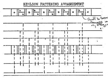
driven from the second or third keelson. Figure 27 gives the arrangement
adopted for the Flying Cloud. It
should be noted that this arrangement is not the same as shown on the Chariot of Fame plan. The keelson
fastening method used in this ship (1853) does not seem to correspond to
descriptions of earlier (1851) methods.
Figure 27 - Keelson Fastening Arrangement
Material Southern pine (see
MAIN KEELSON).
Size The BDA reports the Flying Cloud had two sister keelsons,
the first 16 by 10 and the second 14 by 10. This nomenclature in the great
majority of cases cited by the BDA, means molded 16 and 14 sided 10. Such an
arrangement fits the keelson better than would be the case if the timbers were
sided 16 and 14 and molded 10. Therefore the sister keelsons are assumed to
have been sided 10 inches (see Figure 24 (A)).
Length The main keelson and
sister keelsons were undoubtedly made from about the same length timbers. Thus,
we have assumed 40 feet to be the nominal length of these timbers (see MAIN
KEELSON).
Taper Most BDA reports
imply, although none of them actually so state, that sister kelsons extend as
far as possible in the extremities of the ship, This naturally would
necessitate their being tapered to fit the form of the ship; Wilson206
states that sister keelsons extend forward and aft until the outer edge becomes
6 inches in depth, the top being parallel with the top of the main keelson and
from 6 to 9 inches below it. It has been assumed that the sister keelsons
extend as far as possible. Although they provide no strength in the
extremities, they do fill up places in which rot could start.
Scarf The BDA report of the
Champion of the Seas and the Star of Empire state that the keelsons and sister
keelsons were scarfed and keyed.
Thus, the same specifications have been adopted as those for the main
keelson. They should have proper
shift of butts with respect to both themselves and the main keelson (see MAIN
KEELSON).
Fastening The BDA reports
that the Flying Cloud's sister
keelsons were cross bolted at right angles and diagonally. By comparison with
other BDA reports, it is clear that this means that fastenings went
horizontally through each sister keelson and the two lower depths of midship
keelsons, vertically through both sister keelsons and probably the floor
timbers, and diagonally from the outer angle of the sister keelson through the
navel timbers, blunt into the keel. The timbers through which the vertical
bolts passed were not specified, but Wilson206 says these bolts
(copper) rivet on rings on the outside of the garboard strake, the vertical
bolts are considered to have-been clinched under the navel timbers. This conclusion was based on the fact that
no contradictory reference to this method was found and on the statement that
the Dauntless BDA had her
garboards bolted through every floor timber, with no mention of the sister
keelsons. Thus, these bolts could be iron. The horizontal bolts were undoubtedly
iron since they were entirely within the hold as would be the scarf bolts.
These bolts (horizontal) were about 5 feet apart according to Wilson206
driven, on alternate sides and riveted on rings. The diagonal bolts were driven blunt into the keel, which
would permit them also to be iron.
Material With lack of any
definite evidence to the contrary, it has been assumed that these timbers were
white oak. Although it might seem that the stem and stern post should be of the
same material as the keel (rock maple), various BDA reports and the Chariot of Fame plan indicate that all
of these timbers should be of white oak, and Hall88 indicates that
this1 was the case in the Champion of the
Seas, while the keel was of white oak and rock maple.
Arrangement The stem is the
foremost boundary of the ship, being a continuation of the keel to the height
of the vessel at the fore extreme of her. The apron is placed next aft the stem
to strengthen it, and is actually a part of the fore deadwood. Having fixed the
position of the last square frame, the deadwood becomes the foundation against
which the cants are butted. The stemson is a curved piece placed in the angle
formed by the apron and upper piece of deadwood or keelson.
The stern-post forms the after
boundary of the ship, being the after continuation of the keel. The inner post
is worked inside the main post, with the stern post knee placed in the angle
formed by the keel and stern post. If the inner stern post runs to the keel,
the knee was placed next to this.
Size Griffiths54 states that all stems and
posts should side larger at the head than at the keel, but implies that few of
the builders follow his example. The only specific reference to this
arrangement was given by Hall88 where he gives for the Champion of the Seas only one siding for
the stem, but says that the stern post sided 16 inches at the keel, 20 inches
at the top. Since the MIT and Hall plans show no taper, parallel siding has
been assumed. Thus, both the stem arid post are sided 16 inches.
The BDA reports that the Mystery had a stem molded 27 inches at
the foot and 15 inches at the head, and a stern post molded 29 inches at the
heel and 18 inches at the head, while the Golden LightBDA had a stem
molded 26 at the foot and 14 at the head, and a stern post molded 27 at the
heel and 18 at the head. The Chariot of
Fame plan shows the stem and stern post moldings varying less than the
above, and the arrangement of the Flying
Cloud has been assumed similar to the Chariot
of Fame.
Peake21 and Wilson
advise that the apron and stem should be of the same siding, and Wilson says
the inner post is the same size as the stern post. Griffiths122 recommends that the apron be sided
within one or two inches of the diameter of the bowsprit, or 27 to 26 inches in
the case of the Flying Cloud.
However, he allows for the cases where this is not done by suggesting chocks be
fastened to furnish the required thickness. Hall88 states that the Champion of the Seas had a stem sided 16
inches but an apron sided 30 inches at the bowsprit. The bowsprit was 40 inches
in diameter. No indication was found that the stem and apron of the Great Republic were of different siding.
It has been assumed that the stem and apron of the Flying Cloud were of different siding, essentially following
Griffiths' suggestion by making it sided 26 inches at the head, 16 inches at
the foot.
Length The Westward Ho, Chariot of Fame, and Great
Republic, all had stems and stern posts of single pieces. It has therefore
been assumed that the Flying Cloud
was similarly outfitted.
Scarfs The arrangement for
the stem scarf has been taken directly from the Chariot of Fame plan. A lock scarf is shown for the stem in the Chariot of Fame plan and has been
assumed valid for the Flying Cloud.
Griffiths states that the former
practice of mortising the post to the keel is seldom practiced, rather it is
attached similar to the stem, i.e., with a root scarfed to the keel. However,
only one or two references were made in the BDA reports to a stern post with a
root scarf. Wilson190 states that the stern post is in one piece,
having two tendons cut on the heel of it, and let into the keel and
additionally secured by a composition dovetailed plate let in flush on each
side and through bolted. Fincham12 gives this same arrangement
stating in addition that the tendons are ¼ the depth of the keel in length, ⅓ the
breadth of the keel athwart-ships, and twice their thickness wide, and between
the two tendons the wood was left of the same breadth with them about ¾
of an inch down, which forms a stop for the caulking. The dovetail (mixed
metal) is let in flush and fastened with six bolts through both plates. The Chariot of Fame plan shows a
semi-mortised post as does the Great
Republic plan. The Chariot of Fame
arrangement has been assumed valid.
Fastening Both the Champion of the SeasH88 and
the Great RepublicS11 had
their stem and stern timbers and the Champion
of the SeasH88 had her deadwood, fastened with 1¼ inch
bolts, the same as used for the lower keel sons. The John BetramBDA Bald
EagleBDA and Great
RepublicS11 had their stem, cutwater, apron, stemson, stern
post, false post, and stern knee cooper bolted up to the load line. The bolts
of the Champion of the Seas were 18
inches apart, those of the John Betram
averaged 12 inches and those of the Great
Republic 6 inches, and those shown in the Chariot of Fame plan were about 10 inches. Wilson189
states that the apron is secured to the stem with bolts clinched on rings on
the front of the stem. The stem, apron, deadwood, and stemson are secured
together with through bolts clinched on rings on the front of the stem and
bottom of the keel. The sternpost knee is bolted through the stern post and
keel with two copper bolts in each before the deadwood is put on. The inner
post is fastened to the stern post. The fastening arrangement shown on the Chariot of Fame and Great Republic plans have been accepted for these scarfs
The bolts up to somewhat above the
load displacement line were generally of copper according to the PDAJ above
this they were of iron. In order to determine where this line was on the Flying Cloud, the FDA descriptions of
the Westward Ho and Winged Racer amid to Hall's80
description of the Great Republic are
resorted to. The Westward Ho was
sheathed up to 20 feet and copper bolted up to 21 feet. The Winged Racer was
sheathed up to 21 feet aft and 20 feet forward, and copper bolted up to 22
feet. The Great Republic was sheathed
up to 25 feet and copper bolted up to 26 feet. Thus, it may be assumed that copper fastening generally
extended one foot above her sheathing. Unfortunately, however, the BDA report
of the Flying Cloud makes no mention
of how high the sheathing came. Thus, the water line shown in the plan of the Great Republic must be compared with the
figures mentioned above. The load water line of the Great Republic measures 21 feet forward and 24½ feet aft.
Therefore, it may be assumed that the Flying
Cloud was copper fastened 1 foot above the load water line shown on the MIT
plan.
Material The BDA states that
the frames of the Flying Cloud were
"mostly of superior white oak." "Mostly" is a puzzling
word, and it leaves considerable question as to what parts of the frame were
not white oak. The only clue is
offered in the BDA description of the Stag
Hound where her top timbers are of hackmatack; but the bulwark stanchions
of the Flying CloudBDA
were of white oak. Thus, it must be assumed that in the Flying Cloud all of the frames were of white oak.
Size The size of the floor
timber on the keel is given by the BDA as averaging 12 by 17, or by bur usual
convention, sided 12 molded 17. The
majority of the other BDA reports give a 2 inch spread in the siding and for
the Stag Hound, a 2 inch spread was
given for the molding also.
Considering this and statements made by Griffiths, there seems to be
sufficient justification for assuming that there was a reduction in the molding
of the floor timbers in the extremities of the ship.
There are two possible arguments as
far as the siding dimension is concerned. The Staffordshire had a spread in the siding of 1 inch. The other
reports gave a 2 inch spread to the siding, therefore a 2 inch spread has been
assumed valid for the Flying Cloud.
Since 12 inches is presented as an average, it would seem perfectly justified
to say that the siding was 11 to 13 inches; however, since the great majority
of the floor timbers were the same size, decreasing only at the ends of the
ship, the size of this majority might be quoted as the average. This would make
the spread 10 to 12 inches, the same as that given for the Stag Hound. Another source which should be considered in this
discussion is the plan of the Chariot of
Fame. The space shown between timbers in the center portion of this ship
averages 3 inches (they vary and it is thus impossible to be absolute about
this distance). The room and space (distance between frame centers) of the Flying Cloud is shown in both the MIT
and Hall plans as being l½ feet. If the 12 inch floor timber siding is
assumed, the space between the timbers on the keel would average 3 inches. On
the basis of correlation with the Stag
Hound and the Chariot of Fame, a
siding of 10 to 12 inches has been accepted as most probable: 12 inches
midships, decreasing to 10 inches at the ends.
It is obvious from the FDA reports
of McKay clippers that there was a tendency towards increasing the floor timber
molding. Table 6 presents the molding of the floor timbers of six of McKay's
ships, listed in order of launching date
Table 6 - Floor Timber Molding
Stag Hound 14
- 16
Flying Cloud 17
Staffordshire 18
Flying Fish 18
Sovereign of the Seas 19
Westward Ho 18
Bald Eagle 19
If the 17 inches given is an
average molding, then the spread would probably be 16 to 18 inches
(corresponding to the Stag Hound)
giving for the six ships considered a sequence of molded dimensions midships of
16, 18, 19, 19, 20, 18, 20. However, if 17 inches is taken as an absolute
molding midships, the sequence would be 16, 17, 18, 18, 19, 18, 19. Because of
the higher symmetry which it imparts to the sequence of molding dimensions and
because the sided dimension was taken as valid midships, 17 inches has been
accepted as the floor timber molding midships, decreasing at the extremities.
To arrive at the scantling
throughout the entire frame toe size at both the keel and planksheer must be
determined. Griffithsl02 suggests that after setting these
dimensions it was usual to graduate the molding evenly over the entire length.
In the Flying Cloud, the scantling of
the frame at the keel has been found to be molding 17 siding 12 inches. The size at the planksheer has been
determined to be molded 8, sided 10 inches—see BULWARKS. Hall88
gives a typical tapering of the molding for the Champion of the Seas: keel 20
inches, bilge 13, lower deck 1½, middle deck 9, planksheer 7, rail 6.
Figure 28 gives a skeleton midship cross-section (straightened out) of the Champion of the Seas derived from the
BDA and Hall's description of the ship. Figure 29 gives the midship
cross-section taken from the Chariot of
Fame plan, and Figure 30 gives the midship cross-section taken from the Great Republic plan. Figure 31 presents
the assumed scantling graduation of the Flying
Cloud.
The siding was not diminished
gradually, but rather was reduced at one or more butts, i,e., a futtock would
be sided the same throughout its length, but not necessarily the same as the
adjoining futtocks. The number of reductions required depended upon the amount
of difference between the siding at the keel and at the planksheer. Siding of
floor timbers is taken as 12 inches, decreasing to a siding of 10 inches at the
planksheer. Although Hall's88 description of the Champion of the Seas indicates that the
floor timbers and first futtocks were not of the same siding, the Chariot of Fame plan shows these timbers
to be of equal siding and this arrangement is also true of the Great Republic plan, and has been
assumed for the Flying Cloud
primarily because it is believed this was the usual method. It has been assumed
that the futtocks had the following sidings: floor timbers and first futtocks
(navel timbers) 12, second futtocks 11½, third futtock 10¾, top
timbers (at planksheer ) 10 inches.
Figure 28 - Molding of midship frame - Champion of the Seas
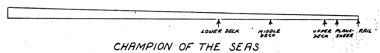
Figure 29 - Molding of midship frame - Charriot of Fame
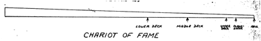
Figure 30 - Molding of midship frame - Great Republic
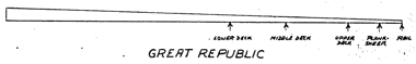
Figure 31 - Molding of midship frame- Flying Cloud
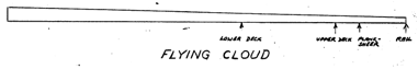
However, the outsides of any frames
are parallel, the reduction in siding occurring on the side of the timber
toward the center of the frame,
Arrangement Griffiths
advocates that the spaces between all timbers be equally divided. The Chariot of Fame plan shows the timbers
of each frame being separated but not quite as much as the space between
frames. An arrangement similar to that shown for the Chariot of Fame has been assumed; 2½ inch spaces between
timbers and a 3½ inch space between frames at the keel.
Because only the center line of
each frame is designated in the draught, it is necessary to determine how
timbers were moved to obtain ff" this spacing. Griffiths111
tells us that the first futtook (which in the Chariot of Fame plan is on the forward side of the frame in the
after body and appears to be on the after side of the frame in the fore body)
moves forward in the after-body and aft in the fore-body. This requires that
the first futtock be placed on the after side of the frame forward of the
(dead-flat) frame and on the forward side aft of the frame. Such an arrangement
would require a larger space to be provided at the frame, which is evident in
neither the MIT nor Hall plans. Since the Chariot
of Fame plan shows this arrangement, it has been adopted for the Flying Cloud. However, the only way that a uniform spacing can be attained
with this arrangement consistent with the MIT plan is to move the first futtock
forward in the after-body and move the floor timber forward in the forward
body.
Length The length of each
futtock is somewhat dependent upon the available timber. A set of dimensions of
individual futtocks was given in Webb's books of plans. It is well known that
Webb did not compile these two volumes until well after the clipper ship period
had passed (around 1890), but there is sufficient detail given in the futtock
diagrams that they may be considered fairly representative of the lengths and
forms available during the 1850's. All of the futtocks adopted for the Flying Cloud are believed to have been
available at the time; each of them is slightly smaller than the futtocks shown
by Webb. The lengths of the
futtocks have been set midship as follows: floor timber 21’-2”, first futtock
17'-6", second futtock 13’-7", third futtock 14’-9”, top-timber 13’-4”,
half-top timber 5’-3”, or bulwark stanchion 10'-3". Hall88
gives the length of floor timbers in the Champion
of the Seas as 24 feet, while giving 25 feet as the length of both the
floor and first futtocks of the Great
Republic. The timbers of the Flying
Cloud would not have been as long as 25 feet since the ship was smaller and
had a greater dead rise. The arrangement adopted for the Flying Cloud coincides very closely with a diagram in GriffithsP1.15.
Scarfs Griffiths139
implies that futtocks were but joined square, not scarfed with a chick as was
the practice in England. The
futtock diagrams shown by Webb imply that the futtocks were plan butted, and
the BDA reports of the Westward Ho
and Bald Eagle and Empress of the Seas speak of frames
being chocked at every joint. Butt joints have been assumed for the Flying Cloud.
Chocks The BDA reports of
the Westward Ho, Bald Eagle and Empress of the
Seas speak of their frames being chocked at every joint. The BDA stated
that the frames of the Lightning were
"chocked with oak above and below every joint". Wilson203
states that chocks were placed between the frames, opposite to each butt, 6
inches thick, dove-tailed ½
inch into the timbers they abutt, the grain of the wood being fore and
aft, keeping the chocks 1 inch clear of the outside of the frame to prevent water
from lodging; trimed fair inside. GriffithsP1.15 shows a number of
frames with chocks fitted between timbers of each frame. Large chocks
(2¾ times as long as the siding of the frame, 2½ times as long as
the molding, or 3 times as long as the chock siding) are shown in the wake of
each joint. Smaller chocks
(½ the length of the larger chocks) are fit ted between each butt chock.
No chocks are shown between frames. It has been assumed that the chocks were
fitted at the joints of each frame timber, but not between frames. These chocks
would be kept 1 inch clear of the frame outside and trimmed fair inside, were
of oak, and of lengths following the proportions shown by Griffiths. Chocks
placed between the joint chocks have been adopted on the basis of the LightningBDA report and
GriffithsP1 •15.
Fastening Hall88
states that the frames of the Champion of
the Seas had from four to seven iron bolts in each futtock, from 1 to 1⅛
inch in diameter: frames of the Great
RepublicH89 were dowelled with white oak cylinders 3¼
inches in diameter, 3½ inches long and bolted through these with 1 inch
iron bolts. The BDA report of the Challenge
states that her frames were bolted with 1 inch iron, and the frames of the LightningBDA and Empress of the SeasBDA were
bolted together fore and aft. GriffithsP1.15 shows one frame bolt
driven through each futtock end and one bolt through each small chock. Wilson197
states that the timbers of the frames are close together and each lap or scarf
is bolted with three iron bolts. These bolts are three inches less in length
than the siding size of the frame and are punched in l½ inches, taking
care to keep them clear of the lodge knees and water-way bolts. The heads and
heels of all the timbers are coaked together with round coaks, and there is a
three inch coak between the timbers at each frame bolt, the bolt passing
through the timbers and coak. The coaks are made of oak, locust, or lignum
vitae.
The following arrangement has been
adopted for the Flying Cloud. Frames have separating chocks between
timbers, with 1 inch iron bolts 3 inches shorter than the width of the frame,
driven in 1½ inches.
Griffiths139 states that
a l½ inch hole should be bored through all butts of the frame. The
direction of these holes should be diagonally from corner to corner of the
butt, half out of each timber, i.e., a hole starting at the molding edge in the
outside should come through at the bevelling edge on the inside. Treenails were
inserted thereby obtaining the strength often achieved by other methods of
dowling, but this method is considered preferable to any other method. Since no
other reference to this procedure was found, we have not adopted it.
Limbers Limbers are openings
cut in the floors of frames to permit drainage of the bilge water to the pumps
midships. Curtis63 states that there were two types of limbers used,
both of them being in the wake of the center of the garboard for the entire
length of the ship. The first consists of a square hole cut out on the bottom
of the floor timbers and first futtocks, while the other arrangement is to
drill a hole a short distance up from the bottom. He states that the limbers
are usually fitted with ⅜
inch diameter close link chain which when fastened is left slack so that the
chain may be moved back and forth to clear the limbers should they become
clogged. The square limbers and ⅜
inch chain have been adopted.
Wilson237 states that
bulwarks are those portions rise above the spar (upper) deck.
Material The BDA states that
he Flying Cloud’s bulwark stanchions
were of oak. It has been assumed
that this was whiter oak, as this material was specified for the rest of the
frame.
Size the size of the bulwark
stanchions of the Flying Cloud is
difficult to determine from the information available. Table 7 presents the dimensions of the
top-timbers at the planksheer for various ships, as given in the BDA reports.
Table 7 - Size of "top timbers"
SIZE
OF “TOP-TIMBERS”*
Stag Hound 8 by 1 0
Westward Ho 10
by 7
Whistler 10 by 6½
Dauntless 6½ by 1 0
Flying Childers 7 by l 0
John Bertram 10 by 7
Great RepublicH89 8 by 11-13
Champion of the SeasH88 7 by 10
*Usual convention is molded by
sided
Because of similarities in other
respects between the Flying Cloud and
the Stag Hound, it has been assumed that the bulwark stanchions were molded 8,
sided 10 at the planksheer.
Height The height of the Flying Cloud’s main rail is given by the
BDA as 5 feet from the deck. The usual convention, and one shown on the Chariot of Fame plan, was to measure,
from the under side of the planksheer, to the under side of the main rail, and
since 5 feet checks fairly well on the MIT plan (5’-1”) and better on the Hall
plan (5’-0”) it has been assumed that the convention is valid.
Taper Hall88
states that the Champion of the Seas
had bulwark stanchions which at the planksheer were molded 7, sided 10 and at
the rail were molded 6, sided 9. The same taper has been given the Flying Cloud. Thus the stanchion at the rail would be molded 7 sided 9.
Arrangement Bulwark
stanchions may be either separate stanchions placed above the upper deck for
the purpose of supporting the bulwarks, or they may be extensions of the
top-timbers above the planksheer. The BDA descriptions of the Queen of the Seas (1300 tons) and the Queen of Clippers (2300 tons) state that
their bulwark stanchions were the continuation of every other top timber, while
the stanchions of the Dauntless (800
tons) were of every third top timber. Because of the similarities in size of
the Flying Cloud and the first two
ships it has been assumed that her bulwark stanchions were the continuation of
every other top timber, or one in every other frame. This places the stanchions
5 feet apart on centers. The only difficulty with this arrangement is the
question of what happens when the first futtocks are switched from the forward
side of the frame to the after side in the usual method of framing a ship.
No solution is proposed.
Fastening A statement that
appeared in the BDA report of the Santa
Claus in regard to fastening the bulwark stanchions to the effect that they
were fastened with composition in wake of the planksheer presents the question
of what the remainder was fastened with.
Material White Oak (see
SQUARE FRAMES)
Size Griffiths states that
both the scantling (in this case of meaning molding) and siding of the cant
frames can be reduced from that of the square frames with advantage. Since it
has already been accepted that the square frames were lighter at the
extremities, it is reasonable to assume that the reduction was carried into the
cant frames. The reduction in molding and siding can be obtained by estimating
the amount of reduction shown on the Chariot
of Fame plan. Although the lines of this ship are not available, making the
results only approximate, it is estimated that in the Chariot of Fame the molding at the keel was reduced from 18 inches
in the square frames to 13½ inches at the extremities. A proportionate reduction for the Flying Cloud would be from 17 to 13
inches molding.
Length Although the cant
timber lengths generally follow the square frame sirmarks, it is desirable in
the extremities to have one timber extend over two or three sirmarks.
Taper The Chariot of Fame plan shows the cants
tapered to the same size at the planksheer as the square frames. This
arrangement has been adopted for the Flying
Cloud.
Fastening Wilson203
advises that the heels of the cant frames are boxed into the deadwood about
l½ inches for a length of 18 to 24 inches. The heel of each timber is bolted through the deadwood with
2 copper bolts and riveted on rings on alternate sides. Hall88 says
that the cant frames of the Champion of
the Seas were tendoned and bolted to the deadwood with 1⅛ inch bolts. Curtis60
gives us a bolting arrangement which shows three through bolts to each timber
arranged in a diagonal line. The cants are assumed to have been tendoned to the
deadwood and bolted with two 1⅛
1inch copper bolts riveted on rings on alternate sides.
Chocks Griffiths115
states that the introduction of chocks in the cant frames is recent, but it has
been assumed not so recent that they were not used in constructing the Flying Cloud. Therefore chocks are
assumed to have been fitted in the same manner as in the square frames, except
that the chocks would be tapered to fit.
Material The Westward HoBDA had her knight
heads of white oak and white oak
has been accepted as the material for the knight heads of the Flying Cloud (see SQUARE FRAMES).
Size Wilson201
states that the knight heads and stem pieces are made conformably to the
scantling of the frame, in and out (molding) except at the upper ends where
there is an additional substance termed the boxing, equal to the thickness of
the outside and inside planking, in the wake of the bowsprit, extending from
about one foot above to one foot below the bowsprit. This wood is left to
prevent joints in the hole for the bowsprit. Griffithsl23 reports that the molding size of the
knight heads should be the same as the adjacent cants, except that in wake of
the bulwark planking, the knight heads should mold an additional amount equal
to the rabbet of this planking that the stem will not be injured immediately
below the bow sprit. It has been assumed that they were sided the same as
adjoining cants or 10 inches.
Arrangement The BDA states
that the Flying Cloud measured 235
feet "from knighthead to traffrail" implying that knight heads did in
fact extend above the bulwark planking. Otherwise, they probably would have
given the dimension as "over-all" as was done in a number of cases.
The sides of the knight heads stand fore and aft and they heel against the
forward cant frame.
Fastening Wilson202
states that knight heads and stem pieces are bolted and coaked to the stem and
apron. The bolts pass through one knight head and the stem or apron only.
However, it would seem that in most cases where possible through bolts would be
used. Curtis59 states that knight heads are bolted through the apron
and stem and each other, and this arrangement has been adopted. 1⅛ inch iron bolts have been
assumed since the Westward HoBDA
reportedly was fastened with iron and the Champion
of the SeasH88 had similar timbers in the stern fastened with 1⅛ inch bolts (see STERN
FRAMING).
Material White oak (see
SQUARE FRAMES)
Size The only size criteria
of the hawse pieces is that they should not be cut off by the hawse hole i.e.,
there should be two hawse pieces such that the hawse hole may go through only a
portion of each. The molding is the same as the forward cant, against which the
hawse pieces heel. The hole
through the hawse pieces is about 20 inches in diameter (see HAWSE HOLE).
Arrangement Wilson203
states that the hawse pieces are the cant frames to the number of 6 or 7 next
aft of the knight heads; they either heel against the fore side of the foremost
cant timber or run down and take the common stepping with the cants. The
forward hawse piece generally sides against the knight head. However, it does
not appear that this practice was followed in the Chariot of Fame plan, since there are spaces between all frames at
the planksheer. Thus, we can only assume that the hawse hole was chocked around
rather than put through solid timbers. The same arrangement appears to be true
for the Great Republic. Therefore, in the Flying Cloud it has been assumed that the hawse holes went through
chocks only.
Fastening All timbers
heeling on the forward cant would probably be plain fitted to it, since any
other method would considerably weaken the cant itself. In addition, each
timber necessarily would be fastened thwart-ships in some manner. Wilson203
states that the hawse pieces were bolted to the apron and to each other with
iron bolts, which should be kept clear of the breast hooks and hawse holes. It
has been assumed that ⅛
inch iron bolts (the size used for cants) were used for these timbers.
Material White oak (see
SQUARE FRAMES)
Arrangement Griffiths127
says it was common practice to cant the frames all around the stern of a round
stern ship; this is the practice shown on the Chariot of Fame plan. Wilson196 states that ships with
elliptical sterns have the common cant frames continued round to the stern
post, and up to the top-sides, thus avoiding entirely the necessity of
transoms. Wilson191 also states that in round and elliptical sterns,
timbers called side counter-timbers are worked on each side of the stern post,
to form the rake and contour of the stern. These timbers butt against the last
cant frame, which heels on the deadwood. Between these side-counter timbers
there was a centre counter timber large enough to fill up the space between
them and upon this centre timber there was sufficient wood left to cut the
rabbet. The counter timbers were securely bolted to each other and the stern
post, and the rudder post was cut through the centre one.
Size Hall88 gives
some dimensions of the stern timbers used in the Champion of the Seas: inner stern post molded 20 inches at the
head, 16 at the foot; stern post sided 20 at the head, 16 at the keel, molded
21 at the top, 24 at the keel; stern timbers at the side of the post 10 by 10;
other stern timbers 10 by 10. Since the square frames of this ship were molded
7 sided 10 at the planksheer, while the frames of the Flying Cloud are assumed to have measured 8 by 10 at the
planksheer, it seems justified to assume that the stern timbers of the Flying Cloud were at least 10 by 10. In
lieu of other specific dimensions, except those obtainable from the Chariot of Fame plan, all of the above
stern frame dimensions have been accepted as valid for the Flying Cloud (except for the increase in siding at the top of the
stern posts).
Thearle106 states that
stern timbers should be canted to follow a conical surface to allow windows to
be properly canted. PaaschP1.8 shows stern timbers vertical as does
Curtis68. We have assumed vertical stem timbers for the Flying Cloud.
Curtis68 suggests that
chocks be fitted in the stern frame in wake of the knuckle and rim, a practice
which is not contradicted by contemporary descriptions of stern framing and has
been adapted for the Flying Cloud.
Taper Hall's88
descriptions of the Champion of the Seas indicates
the stern frame timbers had no taper.
Fastening Hall88
tells us that the Champion of the Seas
had her stern post fastened to the keel with 16 bolts of l½ inch copper.
This can only mean that the stern-post knee, with arms 16 and 7½ feet
long and molding 46 inches at the throat, was thus fastened to the keel. The
stem timbers at the side of the post were through fastened with 1⅛ inch bolts. The same size
bolts have been assumed (see KNIGHT HEADS).
Material It has been assumed
that the reference to a scantling of southern pine applies to planking as well
as the fore and aft thickwork already mentioned. Griffiths143
partially confirms this by stating that it is quite common to plank first class
steamships with yellow" pine, and Hall88 states that all the
planking on the Champion of the Seas
was of pitch pine.
Size The BDA states that the
garboards of the Flying Cloud were 7
inches thick, but there is no indication of how wide these were. Table 8 presents the dimensions of the
garboard and of those strakes next to the garboard for a large number of ships
described by the BDA.
Table 8 - Dimensions of garboards
DIMENSIONS OF GARBOARDS
Golden Light 7 x 12 6 x 12
Storm King 7 x 13 6 x 13
Mystery 7 x 13
Whistler 7 x 14 5½ x 14 5½ x 14
Golden Eagle 7 x l4
Dauntless 7 x 14
Grace Darling 7 x 14
Polar Star 7 x 14
Winfield Scott 7½ x l 3
Lightning 8 x 12 7 x 12 6 x 12
Don Quixote 8 x 14 7 x 12 5 x 12
Amphitrite 8 x 14
Empress of the Sea 8 x 16
Champion of the Seas 9 x 15 8 x 14 7 x 14
It has been assumed that the
garboards of the Flying Cloud were 7
x 14 inches since this seems most likely from Table 8. The BDA also states p
that the next strake outside the garboards of the Flying Cloud was 6 inches, and the next was 5 inches; beyond this
is 4½ inch bottom planking.
An examination of Table 8 indicates that all the thick strakes near the
keel tend to be of equal width. However, no strake measuring 5 x 14 is found in
the table and it seems that this strake would more likely have been 5 x 12 or 5
x 13. The 5 x 12 has been chosen because a strake of these dimensions is found
in the table (Don Quixote). The table
also in dictates that the width of both outside strakes should probably be made
equal.
Length There is little
indication of the length of either the garboards or any other planking on the
ship, outside or in. The minimum length which any plank may ha-we in the case
of the Flying Cloud (with a room and
space of 2½ feet) is 25 feet. This would allow that butts in adjoining
strakes to have 3 frame spaces between them, butts in the next strake but one
would have 2 spaces, and butts in the next strake but two would have 1 space,
while every fourth strake would butt on the same frame. Thearle227 tells us that
Lloyd's rules would not allow adjacent butts closer than 6 feet, while butts
separated by one strake could be 5 feet.
The above arrangement gives separations of 7½ and 5 feet respectively. Planking longer than 25 feet was
undoubtedly readily available and it is probable that the above arrangement
would have been expanded. If the above arrangement is expanded by two times
planking 50 feet long would be required which is probably as long as anyone
would want to handle. The same
general arrangement would also be valid for expansion by one and one-half times
or planking 37½ feet long, which is within the range of lengths
suggested by Wilson216 for the bottom plank. Fifty feet has been
adopted as the length of the bottom garboards and two thick strakes" out
side of it .
Taper Curtis165
states that the garboards, as well as the rest of the bottom planking was run
with either no lengthwise taper or an irregular taper. It has been assumed that
the garboard had no lengthwise taper.
Wilson187 states that the thickness of the garboard strakes
was greatest amidships next to the keel, but diminished gradually in both
directions so as to correspond with the thickness of the plank fore-and-aft and
on the bottom. Peakel3 suggests that the hood-ends be reduced to
¾ of the thickness midships, a figure which has been accepted for lack
of any better. Curtisl75
confirms tapering in this manner, and this plan has been adopted.
The taper athwartships is difficult to fix precisely, since
various contemporary articles do not agree. The BDA states that the Chariot of Fame has 8 inch garboards,
with a 7 inch and a 6 inch strake outside. The Chariot of Fame plan shows the garboard about 8-9 inches thick, but
the next strake is the thickness of the bottom planking - 5 inches. The Great Republic5 had a
garboard 10 by 14 inches with two strakes of 9 and 8 inches outside. However,
the Great Republic plan shows bottom
planking butting on the keel. Thus, one is left with the BDA descriptions,
which taken over-all, seem to leave the feeling that if the garboards were
tapered there was mention made of the fact.
Fastening Although the
garboard fastening of the Flying Cloud
was not specified, an examination of the BDA reports provides the most probable
arrangement as follows: her garboards are let into the keel, are alternately
bolted through each other and the keel, and are square fastened (riveted) with
bolts upwards through the timbers. The ChatsworthBDA
had her garboards cross bolted through the keel every 4 feet with ⅞ inch copper, the same size
as her butt and bilge bolts. The DauntlessBDA
and the Polar StarBDA had
their garboards fastened through their floor timbers. The Dauntless was fastened with 1¼ inch copper bolts. Her
keelsons were also fastened with 1¼ inch bolts. Since the Keelson
fastening of the Flying Cloud was of
1¼ inch bolts, it has been assumed that the garboards were fastened
likewise. It has been assumed that 1 inch bolts were used to bolt the gar
boards horizontally through the keel since this is the size that has been
assumed for the butt and bilge bolts.
Scarfs One authority states
that the garboards and the first inside strake are scarfed, while the next
strake (thick) is butted.
Material The BDA reports of
the Flying Fish and Westward Ho state that their planking
was of hard pine. It has been assumed that the planking of the Flying Cloud was southern pine (see
GARBOARDS).
Size The BDA reports that
the bottom planking of the Flying Cloud
was 4½ inches thick. The only widths of bottom planking given in
contemporary reports of clipper ships is found in Hall's88
descriptions of the Great Republic,
which had bottom planking 6 by 14 inches. Wilson states that bottom planking
should not exceed 12 inches in width and considers the bottom planking to be
all planking running from the wales to the garboard strake. Figure 32 has been
derived from Table 8 to show graphically what size planks were used on the
bottom of ships near the keel. The circled crosses represent the garboard and
thick strakes assumed for the Flying
Cloud. This has been presented graphically in order to derive a reasonable
width for bottom planking 4½ inches thick.
Figure 32 - Dimensions of Garboards and Thick Bottom
Planking
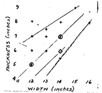
If two lines are drawn which
enclose most of the points of Figure 32, then the extension of a line parallel
to this band but passing through the 6 x 14 inch point (Great Republic bottom planking) to a thickness of 4½ inches
gives a width of 12½ inches, which has been assumed. However, the width
was undoubtedly diminished at the bilge.
There is a difference of 1 inch
between the thickness given for the bottom planking and the wales, which is
twice that given for the Chariot of FameBDA.
The increase is almost imperceptible in the Chariot
of Fame plan. It has been assumed that diminishing strakes were placed at
the turn of the bilge, but as there was only a 1 inch difference, the increase
would take place over only a few strakes.
Length Wilson states that
all bottom planks and all planks in compression are 35 to 40 feet long.
Thirty-seven and one-half feet has been assumed as the nominal length for all
bottom planking in the Flying Cloud
(see GARBOARD )
Taper Curtis begins tapering
planking lengthwise immediately upon leaving the dead flat of the bottom. This
practice has been adopted.
Fitting Wilson215 states that planking terminates in the
rabbet of the stem post and in the rabbet formed by a projection of the center
counter timber. Above the projection of the center counter timber, the plank
runs entirely around the stern. With regard to fitting the planking to the
frames, Griffiths106 states that the bilge strakes should be made
narrower than the bottom planking because of the loss in the scantling size
(molding) of the frame by making it straight for the width of the plank. This
seems to be a very valid argument and is confirmed by Curtis161. This is probably one reason why the
bilge was bolted rather than fastened with treenails since there would be less
wood lost thereby. However, Wilson217 states that in squaring off
the timbers in planking the bottom, the round of the molding edge is retained,
and whatever it is necessary to take away that the plank may lay solid against
the timber is taken out of the plank. It has been assumed that the method
described by Griffiths was used in the Flying
Cloud.
Wilson217 states that
the best plan is to have 11 planks between butts on the same frame, but in no
case should this be less than four. In the method described (see GARBOARDS) there
are 11 planks between butts on the same frame. The BDA report of the Stag Hound
states that "Below, the planking from the opposite sides meets, and the
butts form a series of plain angles down to the stern post." This
arrangement has been assumed valid for the Flying
Cloud.
Fastening Although the
fastening of the Flying Cloud's
planking was not specified, the BDA descriptions of the Staffordshire, Westward Ho,
and the Bald Eagle state that their
planking was square fastened with treenails and butt and bilge with copper
bolts. It may safely be assumed that the same was true of the Flying Cloud. Hall states that the
bottom planking of the Great Republic
was fastened with treenails and butt bolted with 1 inch copper. The ChatsworthBDA with 4 inch
bottom planking was butt and bilge bolted with ⅞
inch bolts. Finchan41 states that planking of a thickness between 3
and 6 inches was bolted with 1 inch copper. It has been assumed that the bottom
planking of the Flying Cloud was butt
and bilge bolted with ⅞
inch copper bolts.
The size of treenails is given by
Curtis178 as from 1¼
to 1½ inches in
diameter depending upon the thickness of the plank. Hall89 says the
planking of the Great Republic was
fastened with 1¼ inch locust treenails through the timbers. For the Flying Cloud 1¼ inch treenails
have been assumed. Curtis178 gives the following directions for
fastening with treenails: they are generally made of black locust, are driven
from the outside through the inside ceiling, and are wedged on both ends with
oak wedged set across the grain of the plank. Treenails are commonly (when
less-than 2 feet long) driven in a hole about 1/16 inch smaller than the
treenail. It is believed they would be located ⅓
of the width of the plank in from the edge and likewise for the width of the
timber. Wilson219
states that all outside planking should be square fastened (two through
and two short fastenings in each frame), short fastenings should be about 2⅓ times the thickness of the
plank, but if let in ½ inch shall not go within 1 inch of the inside of
the frame. In way of knee bolts, water-way bolts, etc. these bolts are omitted.
In the frame next on each side that on which the plank butts, in lieu of one of
the shortest fastenings, in the timber next the butt, there is a through bolt
placed called a butt-bolt. Peake46 suggests the butt should be ⅓ and ⅔ on the timber to ensure
wood for the reception of the butt-bolt in the ⅔
section, the other butt-bolt being placed in the adjacent timber of the frame.
In the hood ends forward and aft, through bolts are driven and riveted on
alternate sides. When plank is reduced to a width of 6 inches, one half of the
short fastenings should be omitted and the remainder placed on the alternate
edges. Copper fastening extended to the iron fastening of the tops. Wilson220
states that below the copper fastening line, treenails made of seasoned locust
are sometimes used; two treenails one bolt and one short fastening through each
frame. Above the copper line two short fastenings and two bolts of iron are
always used. No plugs are put over the heads of bolts outside the lower port
sill. After the vessel is planked the projecting edges of the strakes are all
trimmed off, called squaring off.
Fincham41 states that
the treenails that fasten the exterior planking pass through the timbers and
also form the principal fastenings of the ceiling, but as the exterior and
interior cannot be planked at the same time, the exterior is brought on first.
The holes for the treenails are bored through the outside planking and the
timbers. The outside planking is held to the frame by temporary screw eye-bolt
fastening, to secure it to the frame until the treenails can be driven through
both planking and ceiling. Screw
eyes or screw-bolts are in length, from a shoulder left just beyond the eye,
about the thickness of the plank plus 6½ inches, and have a worn cut on
from their ends about 6½ inches. The diameter of the bolts is 1 inch for
plank 3 to 6 inches thick, and l½ inches for above 6 inches. When the
interior planking is brought on, the holes for the treenails are bored through
it and the screw-bolts are removed as it becomes necessary to drive the
treenails. The treenails have both their ends caulked. The large size is
caulked square, the medium triangular, and the small crosswise. Wilson219
" states that all through (metal) fastening from outside rivet on the
inside planking, waterways, knees, etc.
It has been assumed that the Flying Cloud's bottom fastened with two
l¼ inch locust treenails and two 10 inch short fastenings ½ inch
in diameter in each frame. The treenails were caulked crosswise (+) at each end
the short fastenings punched in ½ inch, but not plugged except above the
water-line, copper was used up to the load line, iron above this. In the bilge
it has been assumed that 1 inch copper through bolts replaced the short
fastenings. At each butt 1 inch copper bolts were used as described above.
Material Southern pine (see
GARBOARDS).
Size The BDA report states
that there were 18 wales 5½ inches by 7 inches. It seems obvious that
these would be placed on the frame molded 5½ inches, which corresponds
to the arrangement shown on the Chariot
of Fame plan and the 5 inches thick and 7 inches wide suggested by
Griffiths143.
Length Since Wilson216
states that wales, clamps, and spirketting are 40 to 50 feet long, it has been
assumed that the wales of the Flying
Cloud were 50 feet in length (see GARBOARDS).
Taper Griffiths106
states that the modern procedure was to taper wales, but admits that not all
builders preferred this over a constant width. The BDA description of the Stag Hound states that "The
planking along the upper part of the run is carried up to the line of
planksheer and there terminates, and this is done without any irregularity in
the width.” This statement implies that the wales were not tapered. Thus it has
been assumed that the wales of the Flying
Cloud were not tapered.
Arrangement It is stated in
the BDA report of the Flying Fish
that the wales were carried up flush to the planksheer. The other BDA
descriptions merely say "planked flush to the planksheer." Griffiths55
recommends flush wales saying that by having no projection to the wale
("and any vessel is better without the projection than with it") a
flush side is least apt to get marred, and the ship is equally as strong. The
BDA report of the Westward Ho states
that this ship was "planked smoothly, without a projection line up to the
covering board", which indicates that the wales did not project over the
bottom planking—an arrangement also shown on the Chariot of Fame plan. The position of the lower edge of the wales
on the Flying Cloud would be
17½ inches below the water-line shown on the MIT plan.
Fastening Fastenings are the
same as for the bottom planking—1½ inch treenails and 1 inch butt
bolts (see BOTTOM PLANKING).
Material It is stated in the
BDA report of the Bald Eagle that her
planksheer was of hard pine. It may be assumed that the planksheer of the Flying Cloud was also of hard (southern)
pine (see GARBOARDS).
Size The BDA specifies that
the planksheer of the Flying Cloud
was 6 by 16 inches. Descriptions of other ships often specify that the plank
sheer was 6 inches thick, and it can confidently be assumed that the same
arrangement is applicable to the Flying
Cloud.
Length The planksheer and
main rail should obviously be in as long lengths as possible. Since some of the
outside planking has been assumed to have been 50 feet long, it is not
unreasonable to assume a length of 60 to 70 feet for the midship portions of
both the planksheer and main rail.
Arrangement One timber of
every other frame extends above the planksheer forming the bulwark stanchions
while the other timbers are cut off so that the planksheer may rest on them.
The stanchions are tapered (see BULWARK STANCHIONS) so that the planksheer may
be gotton over. When in place, the planksheer, main rail, and monkey rail
should all cant to the outside (see MAIN RAIL). The BDA in many cases reports
that the moulding of the planksheer is carried around the stern and this is
shown in all the paintings of the Flying
Cloud and both the Hall and MIT plans show the line of the planksheer
continuous from head to stern. However, Griffiths141 states that the
planksheer in its whole width extended no farther than the stanchions were
single which is where the forecastle and poop decks commence; the whole frames
forming solid bulwarks in the extremities. A molding is continued around both
outside and inside, so that externally, the appearance is the same. This
arrangement is designed to allow all the top-timbers to extend in their full
scantling to the forecastle and poop decks beams. The planksheer is placed so
that it extends ½ inch beyond the wales or 6 inches on the outside of
the bulwark stanchions.
Fastening Griffiths142
states that the planksheer (having been put over the stanchions) should be
bolted edgewise once through each stanchion and at least twice between each
stanchion; and inasmuch as it has no bearing in the center, it should also be
well fastened to the waterway and outside strake. BDA descriptions stated that
fastenings of a number of ships varied from ⅞
to l¼ inches and it has been assumed that ⅞
inch bolts were used for the above fastening. Griffiths arrangement has been
adopted.
Scarfs Griffiths142
states that the siding of the stanchion sets the length of the planksheer
scarf. One nib of the scarf should cut with the side of the stanchion on one
side of the planksheer and the other nib on the opposite side, both of
stanchion and planksheer. Thus, a scarf extends only the siding of one
stanchion, i.e., 10 inches. The nib extends between the edge of the planksheer
and the stanchion.
Moldings The Chariot of Fame plan shows a molding on
both edges of planksheer, main rail, and monkey rail; while both the Hall and
MIT plans indicate moldings of some type. The molding which has been adopted is
the simple one shown on the Chariot of
Fame plan shown in Figure 33.
Figure 33 - Planksheer and Rail Molding
Material Griffiths142
states that the bulwark planking in the bow is usually of oak, however,
southern pine has been accepted as being most probable (see GARBOARDS).
Size The BDA states that the
bulwarks of the Westward Ho and Flying Childers were of 2½ inch
material while those of the Empress of
the Sea were of 2 inch and those of the Queen
of the Seas were of 3 inches. These measurements were undoubtedly the
thickness of the plank states that the outside planking of the bulwark was some
2 inches thick and 3 inches wide midships. The BDA reports often stated that
bulwarks were “tongued, grooved, and beaded in the usual style and that results
look as smooth as glass". Since there is no reason to expect that the Flying Cloud would have been outfitted
differently, tongued and grooved planking 2½ thick and 4 inches wide has
been chose as the most probable.
Length It has been assumed
that the length of the bulwark planking was 37½ feet (see BOTTOM PLANKING).
Taper Griffiths142
suggests that two methods of planking the bulwarks were equally satisfactory.
Parallel widths may be used, starting with the main rail and continuing down
until they shut in aft (for there is more of an opening at the bow); then
progressively shorter parallel strakes were used to shut in forward. The other
method was to divide all planking regularly all around, so there were an equal
number of strakes everywhere. The
latter method would be neater in appearance and therefore has been chosen.
Fastening According to the
BDA the bulwark boarding of the Stag
Hound, Dauntless, and the John Bertram was fastened with composition.
It has been assumed that these fastenings were of the same proportions as the
deck fastenings—¼ inch square, 4 inches long.
Inside Planking There is
question whether the Flying Cloud's
bulwarks were planked inside. The BDA description of the Bald Eagle implies that planking the bulwarks on both sides was the
exception rather than the rule.
DavisDP 96 states that in merchant ships the inside of the
timbers were left exposed below the pin rail and bib-piece under it (a rail
similar to the pin rail but below it). The BDA report of the Sovereign of the Seas makes no mention
of the inside bulwark planking and Lubbock48 in his the Colonial Clippers shows a picture of
this ship with bulwark stanchions visible. It is possible that the Currier
lithograph of the Flying Cloud does
show timbers forward of the forward mast. It has therefore been assumed that
the main bulwarks of the Flying Cloud
were not boarded.
Rack Rail The BDA states
that the Flying Cloud had a rack
rail, and claims that the Dauntless
had a rack rail about 1 foot below the main rail . The Chatsworth had
an oak pin rail 5 inches thick, while the Chariot
of Fame plan shows a rack rail about 6 inches thick and 11 inches wide. How
ever, this was constructed somewhat differently from the way it is believed the
Flying Cloud was arranged since on
this plan the rack rail is placed over 3 inch inside bulwark planking. However,
the same working room and thickness as shown on the Chariot of Fame plan has been provided giving a rack rail 6 inches
thick, 17 inches wide.
Clamp The BDA states that
there was a stout clamp extending fore and aft between the main and rack rails.
This clamp probably extended to the extremities of the ship acting as a support
for the main rail. The fastening of the clamp was undoubtedly the same as that
reported for the Stag HoundBDA
where it was bolted horizontally through the stanchions and vertically between
both rails, indicating that the clamp completely filled the space between the
two rails. Since it has been assumed that the main rail extended 4½
inches inside the bulwark stanchions (see MAIN RAIL), we have made the clamp
molded 3½ inches. To provide the same amount of vertical working space
as on the Chariot of Fame, the clamp
would be sided at least 6 inches. However, to place the rack rail at the same
height from the deck as the Chariot of
Fame, the clamp would be sided 12 inches. Since the rack rail of the DauntlessBDA was about 1 foot
below the main rail, 12 inches has been accepted as the siding of the clamp in
the Flying Cloud.
Material Southern pine has
been assumed (see GARBOARDS).
Size The BDA reports that
the main rail of the Flying Cloud was
6 inches thick by 16 inches wide.
Length 60 to 70 feet (see
PLANKSHEER).
Taper None (see PLANKSHEER).
Arrangement Griffiths141 states that the
rail should have sufficient cant to turn the water outside of the ship, except
on the bow, where it cants less and is set to a straight line across at the
knight heads. The Chariot of Fame
plan shows the cant of the planksheer, main rail, and monkey rail midships as
follows:
planksheer 3½
degrees from horizontal
main
rail 5½ ditto
monkey
rail 6 ditto
These cants have been assumed for
the Flying Cloud. The main rail is
assumed to have been placed symmetrically on the stanchion extending out board
4½ inches from the stanchion.
Griffiths states that when a monkey
rail is to be constructed, the main rail is put over the stanchions much the
same as the planksheer, implying that the stanchions extended to the monkey
rail. However, the BDA reports of many ships referred to monkey rail stanchions
which were of a different material from bulwark stanchions , and the BDA of the
Whistler states that the monkey rail was strongly bolted to the main rail.
Thus, it has been assumed that the monkey rail stanchions were not extensions
of the bulwark stanchions. The main rail is assumed to have been tendoned 1
inch over the stanchions as suggested by Griffiths142. Reference to
the clamp supporting this rail is found under BULWARK PLANKING.
Scarf Griffiths142
states that rail scarfs should be edge-ways, and that he prefers the key to the
hook scarf for this application, implying that he did not agree with most
builders. Since the key scarf was widely used according to the BDA, this type has
been assumed. Curtis's30 rule has been followed giving a scarf 8
feet long with 4 inch nibs.
Fastening It has been
assumed that the fastening arrangement was similar to that used for the
planksheer.
Material Southern pine (see
GARBOARDS).
Height The BDA states there
was a monkey rail of 16 inches surmounting the main rail. By comparing the BDA report and the
plan of the Chariot of Fame, it is
found that this means the top of the monkey rail was 16 inches above the upper
surface of the main rail. Thus, the bulwarks stood 6 feet 10 inches above the
waterway, 4 inches higher than those of the Stag
Hound, 12 inches higher than those of the Flying Fish, and 2 inches higher than shown on the Chariot of Fame plan. The above
arrangement has been accepted. There is an even higher rail shown on the
Currier lithograph and Chinese painting fitted in the bow on top of the monkey
rail. It measures (Chinese painting) 54.5 feet long and the height is in the
neighborhood of one foot
Size Since the planksheer
and main rail of the Chariot of Fame
were about the same size as specified for the Flying Cloud, it has been assumed the monkey rail was the same size
as that shown on the Chariot of Fame
plan, i.e., 4 inches thick by 10 inches wide.
Length The monkey rail
should be made out of fairly long timbers, although it is not added for
strength as are the planksheer and main rail. Fifty feet has been accepted as a
reasonable length.
Scarf It has been assumed that the description of a
scarf given by Griffiths142 for the main rail to be applicable to
the monkey rail (see MAIN RAIL). A key scarf, 5 feet long with 2½ inch
nibs has been adopted. (The monkey rail was planked inside and out according to
Griffiths141. The Chariot of Fame plan shows the outside
planking on the monkey rail to be somewhat less than the corresponding bulwark
planking, while it was paneled inside. It is impossible to tell what is shown
on the Currier lithograph. It has been assumed that the outside planking was 2
by 3 inches. Since most of the pictures of ships did not show stanchions, above
the main tail, a paneled monkey bulwark has been assumed inside.
Clamp The BDA report of the
Whistler states that the monkey rail was solid, clamped inside and outside.
However, it has been assumed that no clamp was fitted inside on the Flying Cloud since none is shown on the Chariot of Fame plan.
Location The Chariot of Fame plan shows the monkey
rail almost flush with the outside monkey bulwark planking. It has been assumed
that on the Flying Cloud it was
placed 2½ inches outboard from the stanchion, i.e., a molding of
½ inch, would be evident.
Material Southern pine (see
GARBOARDS).
Size The BDA states that the
ceiling on the floor of the Flying Cloud
is hi inches thick. The Chariot of Fame
plan shows 5 inch ceiling strakes 12 inches wide. It has been assumed that the
4½ inch ceiling strakes would be about 12 inches wide, (see BOTTOM
PLANKS).
Length Ceiling planking
generally follows the same rules as outside planking; thus, it has been assumed
that 25 to 50 foot strakes are again applicable but 37½ feet has been
assumed as the nominal length.
Taper Same as corresponding
outside planking (see BOTTOM PLANKING).
Scarfs The BDA often
reported that the hold ceiling was scarfed above the thick strakes over the
bilge, but no direct reference to scarfing the floor ceiling was found. Since
the BDA apparently excludes the floor ceiling, it .has been assumed that this
was butted.
Fastening The BDA states
that the bottom ceiling was square bolted. A look at the BDA report of the Stag Hound indicates that this means '"square bolted, not
tacked with spikes". Curtis100 states that the ceiling
fastening is commonly driven in the center of the frame timbers to reserve the
space from the center to the edge of the timbers for the outside planking
fastening, two button-headed bolts driven from the inside to within 1 inch of
the outside of the frame, and two being headed blunt bolts driven from the
outside and clinched over rings on the inside. No reference to the size of this
fastening was found, but it has been assumed that it would be substantially the
same as the butt and bilge bolts for the planking or 1 inch. Copper bolts are
assumed up to 1 foot above the load water line; iron above.
Caulking Although no
specific mention of caulking is made in the BDA report of the Flying Cloud, it has been assumed that
the Flying Cloud was built similar to
the Stag Hound which had "Her
hold ... caulked and payed from the limber boards to the (lower) deck.
Material Southern pine (see
GARBOARDS).
Size The arrangement of the
limber strakes has been patterned after that shown on the Chariot of Fame plan. The lumber strakes shown here are a little
over one-half the thickness of the floor ceiling and span a horizontal distance
just slightly larger than the width of a strake of floor ceiling. Fincham33
states that for 4½ inch ceiling, the limber strakes would be 3 to
3½ thick. It has been assumed that for the Flying Cloud a 3½ limber strake 16 inches wide would be
suitable. Fincham33 claims that limber boards were in about 3 feet
lengths.
Fastening It is believed
that in order to facilitate their removal, limber strakes were not fastened in
any way; the rabbeted edges would hold them in
place.
Material Southern pine (see
MAIN KEELSONS).
Size The only transverse
section of a McKay ship discovered which shows bilge keelsons is that if the Great Republic. The description given by Hall88
states there are “two bilge keelsons, each 15 inches square and in two
depths". The plan shows two double bilge keelsons on each side, making
four keelsons, each of two depths. If the same comparison is followed for the Flying Cloud which on the bilge
"has two keelsons, each 10 by 16 inches," it is clear that there was
a total of four bilge keelsons in the ship. Hall88 says that the
ceiling of the Great Republic was of
10 by 12 inch strakes. The plan shows these strakes to be sided 10, molded 12,
so that it may be assumed that the bilge keelsons of the Flying Cloud were sided 10, molded 16, just opposite to the usual
convention but in this case a more logical arrangement.
Length The lengths of the
individual timbers have been assumed to -be the same as that of the other
keelsons or 40 feet.
Taper Fincham34 says
that bilge thick strakes were reduced to ⅔
of their thickness, starting 8 to 10 feet from the end. However, it was often
stated in BDA reports that the bilge keelson and the other thick strakes
extended to the ends undiminished in size. The latter arrangement has been
assumed. Wilson213 states that all thick strakes rise with the heads
of the timbers and butt under the berth deck lamps.
Scarfs The BDA reports of the Champion of the Seas and the Lightning, and the description of the Great RepublicS13 state that
the bilge keelsons were scarfed, keyed, and fastened as were the other
keelsons, which has been assumed.
Fastening The BDA report of
the Lightning states that her bilge
keelsons were square fastened through the timbers, the bolts being driven
alternately from inside and outside and riveted. Hall's88 and a
Sailor's13 descriptions of the
Great Republic gives the only indication of the fastening arrangements for
bilge keelsons. These were square bolted with 1-¼ inch iron through each
timber and edge bolted with ⅛
inch iron. Since the main keelson of the Great
Republic was fastened with 1-⅜
inch bolts, 1⅛ inch
bolts have been assumed for the bilge keelsons of the Flying Cloud—⅛
inch less than those in the keelson. No edge bolts were assumed (see HOLD
CEILING).
Location Hall’s89
description of the Great Republic and
the BDA description of the Flying Fish,
Westward Ho, and Bald Eagle all specify bilge keelsons as being located over the
floor heads or over the first futtocks.
The location of these keelsons in the Flying Cloud is assumed similar.
Caulking The bilge keelsons
are assumed to have been caulked and payed (see FLOOR CEILING).
Material Southern pine (see
GARBOARDS).
Size It is stated by the BDA
that the hold ceiling from the bilge keelsons to the lower deck damp is 7 inches
thick. It has been assumed that a width of 10 inches for these strakes is
reasonable.
Length The lengths should be
37½ feet (see FLOOR CEILING). Griffiths122 states that the
hold ceiling and clamps may extend over the after side of the apron and butt in
the center, or they may butt (without a rabbet) to the siding edge of the
apron. The latter is preferred by him and has been accepted for the Flying Cloud.
Taper Same as corresponding
planking (see BOTTOM PLANKING).
Scarfs The BDA specifies that this portion of the ceiling of
the Flying Cloud was scarfed. Curtis100
states that ceiling scarfs were 2 frame spaces long (5 feet), flat with the
outboard nib feathered against the frame and the inboard nib being ⅞ of the thickness of the
strake. This arrangement has been
adopted.
Fastening The BDA specifies
that this ceiling was square fastened, and it has been assumed that the
fastening was the same as outlined under FLOOR CEILING. Although many of
McKay's later ships were edge bolted between every other frame, no early
references to this were found and it has been assumed that this was not done on
the Flying Cloud.
Caulking The hold ceiling
has been assumed caulked and payed (see FLOOR CEILING).
Material Southern pine (see
GARBOARDS).
Size The BDA states that
there was a 10 by 16 inch stringer upon which the lower ends of the hanging
knees rested and to which they were fayed. The logical arrangement for this
strake is placed flat, giving 3 inches (a 10 inch strake below a 7 inch
ceiling) for the knees to rest upon, which is entirely sufficient if the
arrangement given in the Chariot of Fame
plan is followed. This arrangement also conforms to the usual "molded by
sided" convention.
Length The stringers must
extend to the extremities of the ship since there are beams and hanging knees
throughout the length of the ship. Timbers 40 feet long have been assumed (see
BILGE KEELSONS).
Taper None (see BILGE
KEELSONS).
Scarf The FDA reports
generally agree that certain thick work was scarfed. The details of the scarfs
are assumed the same as the BILGE KEELSON.
Fastening The BDA reports
state that the thick work of the ceiling of most McKay vessels was square
bolted through the timbers. Bolts 1⅛ inches have been assumed (see BILGE
KEELSONS).
Caulking It has been assumed
that the thick work was caulked and payed (see FLOOR CEILING).
Material The BDA reports
that the Stag Hound had beams of hard
pine, the Flying Fish had beams of
southern pine, and the Westward Ho
and Bald Eagle had deck frames of
hard pine. The Flying Cloud
undoubtedly had beams of southern pine.
Size The BDA states that the
lower deck beams of the Flying Cloud
were 15 inches square. It was common practice to reduce the molding of beams
toward the sides of the ship. Wilson222 states that beams were
molded one inch less at the ends than at the center. The Chariot of Fame plan shows a reduction of 2 inches in each of her
three beams which, starting with the lower deck were molded midships 15, 14,
and 12 inches respectively. Halls'89 description of the Great Republic states that "...the
beams of the lower and main decks (were) 15 by 16 and (15 by) 18 inches
amidships, tapering to 12 inch molding at the ends, while the upper decks
beams...were 12 by 20 inches in the center, tapering to 10 inch molding at the
ends..." The LightningBDA
had lower deck beams 14 by 16 inches amidships, tapered an inch or two towards
the ends. The BDA descriptions of the Staffordshire
and Flying Fish specify that the
dimensions given are of the beams amidships and it is reasonable that this was
also the case in the case of the Flying
Cloud description. A reduction of 15 to 13 inches given by the Chariot of Fame plan has been accepted
as valid for the Flying Cloud.
Camber No consistent
"proportions were discovered for the camber of the beams. GriffithsP1.21
shows both lower and upper deck beams cambered ¾ inch per foot on top,
with no camber on the bottom side of the beams; Curtisll2 suggests
¼ or 3/l6 inch per foot for the upper deck and none for the lower deck;
the Chariot of Fame plan shows ⅓ inch per foot on the
topside of all three decks and about ⅙ inch per foot on the
bottom sides; the Great Republic plan
shows ⅜ inch per foot
on the topside and somewhat less than this on the bottom side. The Flying Cloud would be given a camber of
11/16 inch per foot if the MIT plan and the BDA descriptions are followed. This
camber falls within the other values noted and therefore has been assumed valid.
Since Griffiths and the Chariot of Fame
and Great Republic plans show all
decks cambered equally, it has been assumed that both decks of the Flying Cloud have 11/16 inch per foot
camber. The bottom camber is determined by the molding of the beams at their
extremities.
The value of 11/16 inch for the Flying Cloud was arrived at by combining
the location of the planksheer shown on the MIT plan, the BDA report of the
depth of hold (21’-6" from the top of the floor ceiling at the limber
strake to the top of the upper deck beam), the BDA report of between deck
height (7' - 8" from the upper side of the lower deck to the under side of
the deck above) and the depth of the waterway (14 inches).
Length Since no scarf is
shown in the Chariot of Fame beams,
it has been assumed that 40 foot timbers were readily available for the Flying Cloud.
Location There is no
indication what spacing was given to the beams in the Flying Cloud. Various BDA descriptions (Orient, J. Montgomery, Wizard, Witch of the Wave,
Winfield Scott) indicate that beams
were spaced from 4 to 7 feet apart. The Chariot
of Fame plan shows beams located essentially at every third frame or every
7½ feet. This arrangement
has been adopted for the Flying Cloud.
Fastening Curtis123
and Wilson223 stated that two bolts were driven well into the
clamps. Thus the beams were primarily fastened in conjunction with the
waterways and adjacent strakes.
Material Griffiths141
states that between deck waterways were commonly made of yellow pine, and the
lower deck waterways of the Champion of
the Seas were of yellow pine. Yellow pine has been assumed (see GARBOARDS).
Size The BDA states that the
between deck waterways of the Flying
Cloud were 15 inches square. Over this was a strake 10 by 16, which by the
usual convention would be molded 10 sided 16. This would place the strake over
the waterway flat against the frame, not projecting over it. This arrangement is reasonable since if
the strake was placed the other -way it would project 1 inch over the waterway.
The BDA also said that there was a strake inside the waterway measuring 10 by
14 inches—again presumably molded 10 sided 14.
Length A length of 40 feet
has been assumed for these timbers (see BILGE KEELSONS).
Taper Curtis146
shows- these strakes untapered, even at the extremities (see BILGE KEELSON).
Scarf Wilson228
states that in most cases waterways butt against each other. However, the
description of the Great RepublicS13
states that her upper deck waterways were scarfed and Hall88 states
that the lower deck waterways (molded 15 sided 14) of the Champion of the Seas had 6 foot scarfs. Curtis140 shows
waterway scarfs as being vertical.
The BDA report of the Mystery
stated that her waterways were lock scarfed as well as all her thick work. It
has been assumed that the waterways of the Flying
Cloud had a 6 foot vertical scarf. The strakes over the waterway are
assumed to have been scarfed vertically while the inside strake is assumed to
have been scarfed horizontally. Since these strakes were both molded 10 inches,
the scarf length should be ⅔
of 6 feet or 4 feet.
Fastening The BDA reports
generally state that the between deck waterways were cross bolted, i.e., both
vertically through the strake over the waterway and the beam, and horizontally
through the strake(s) inside the waterway and the timbers. Wilson228
states that they were secured with one up and down bolt through each beam, one
bolt in each beam driven at an angle into the frame and one between the beams
through the knees and into the clamps. Curtis141 gives the following
arrangement for cross bolting the waterways, etc. The waterways received two
button-headed bolts driven from the outside and the inside. The inner strakes
also received two such bolts similarly driven. These four bolts were arranged
in a square on the stanchion (if upper deck) or on the inner edges of the frame
(if between decks). In addition,
two button-headed bolts were driven horizontally through all waterway strakes
into a chock fitted between the stanchions in way of the waterway and resting
on the top timbers. In the between decks, these button-headed bolts were driven
into the frame. Two bolts were driven through each strake and the beam and were
clinched over rings. The BDA
states that the Ellen Foster and the J. Montgomery had their between deck
waterway timbers square fastened horizontally and closely bolted vertically.
The Winged Arrow had her inside
strake let into the beams and was bolted through them and horizontally through
all. The thick work above was
square fastened and bolted vertically into the waterways .
The BDA states that there were 1325
1 and 1¼ inch bolts in the waterways and the beams and timbers between
decks of the Westward Ho. This gives an average density of 3.40
bolts per boot for an estimated waterway length of 390 feet. Similar figures
are given for the Bald Eagle, which
had 1452 bolts through the between decks waterways, timbers, and beams. With an
estimated length of 395 feet, this gives an average density of 3.67 bolts per
foot. With the square fastening arrangement discussed by Curtis and assuming
the beams to be spaced on 7½ foot intervals (see LOWER DECK BEAMS), the Flying Cloud would use 3.00 bolts per
foot, very close to the above figures but indicating that more bolts were used,
probably in the bow and stern.
The Champion of the Seas between deck waterways were fastened with 1⅛ inch iron bolts through
the timbers as were the upper deck waterways. Since the fastenings of the Champion of the Seas were generally
larger than the earlier McKay ships, we have assumed that the bolts were the
same as in the Westward Ho, i.e., 1
and 1⅛ inch iron. It
is thought that a reasonable arrangement would be to use 1 inch bolts for
horizontal fastening through the waterways only and 1⅛ inch bolts for fastening through the waterway
and inside strakes. It has been assumed that 1⅛
inch bolts were driven vertically through the inside strake while 1 inch bolts
were driven vertically through the waterway and strake over the waterway. This
arrangement tends to equalize the large and small bolts driven through any
single timber or strake.
Arrangement Curtis139
states that waterways generally were set square to the beam. Hall88 states that
the between deck waterways in the Champion
of the Seas "lay flat" on the ends of the beams. Wilson228
states that waterways were dovetailed down over the ends of the beams 2 inches.
However, no other reference of this method was found and the Chariot of Fame plan seems to show the
waterways not let over the beams.
Table 9 prepared from BDA reports
gives the mortise thick strake(s) inside the between deck and upper waterways.
Table 9 - Mortise Arrangement
Between
Decks Upper Deck
Stag Hound - let
over
Flying Cloud - -
Staffordshire - -
Flying Fish - let
over
Sovereign of the Seas - -
Westward Ho mortised over let over
Bald Eagle - mortised
over
Since the Stag Hound had her strakes let over the upper deck beams we have
some justification for one over the other for the Flying Cloud, but there is little justification for one over the
other between decks. However, it
is felt that there is a slightly better chance that they were arranged the
same. Thus. It is assumed that the strake was let over the beams in both decks.
Curtis139 states that the lock strake is let into the beam 2 to 3
inches so that the top is flush with the waterway. In the present case it is
impossible to make the top flush with the waterway (see Size), but it
has been assumed that the strake was let over the beams 2 inches.
Material Southern pine (see
GARBOARDS).
Size This section of ceiling
is specified by the BDA as being 5½ inches thick. A width of 7 inches
has been assumed since the Chariot of
Fame and Great Republic plans
show these proportions.
Length Fifty feet has been
assumed (see FLOOR CEILING, WALES).
Taper Same as corresponding
planking (see WALES).
Scarf The BDA makes no mention
of this ceiling being scarfed, but it has been assumed that this ceiling was
scarfed in the same way as the hold ceiling.
Fastening According to the
BDA this ceiling was square fastened, undoubtedly, in the same manner as the
floor and hold ceilings (see FLOOR CEILING).
Caulking Although the BDA
made no mention of caulking this ceiling, it has been assumed that it was in
fact caulked since it is reasonable to have caulked everything possible.
Arrangement Griffiths122 states that all
ceiling and clamps above the lower deck should but against the apron in the
same manner as the outside plank, except with no rabbet. This arrangement seems reasonable and
has been adopted.
Material Southern pine (see
GARBOARDS).
Size According to the BDA
there is one clamp 7 inches thick under the upper deck beams. Its width has
been set at 8 inches from comparison with the clamps shown in the Chariot of Fame plans and those of the Great Republic.
Length, Taper, Scarf,
Fastening. This clamp can be
considered as part of the 5½ inch ceiling for these purposes.
Material Southern pine (see
LOWER DECK BEAMS).
Size The BDA states that
these beams were 9½ by 16 inches amidships. The convention would make
these beams molded 9½ sided 16 inches, a reasonable arrangement
considering that the Chariot of Fame
plan shows the upper deck beams molded 12 sided 17 inches and Wilson222
states that the siding of beams is greater than the molding.
Fastening The Chariot of Fame plan shows these beams
square butted to each beam, (see LOWER DECK BEAMS).
Camber Same as lower deck
(see LOWER DECK BEAMS).
Taper A beam molded
9½ inches would not have been reduced as much at its ends as the larger
lower deck beams. A reduction of only 1½ inches (to 8 inches) has been
assumed. This was the taper given to the upper 1 deck beams (9 x 14) of the King Fisher, while the John Bertram had a 1 inch taper on her
beams (9½ by 16).
Material Southern pine (see
BETWEEN DECK WATERWAYS).
Size The size of this
waterway was given by the BDA as 12 by 14 inches, or by the usual convention
molded 12 sided 14. This convention is confirmed by the Chariot of Fame and the Great
Republic plans. These
dimensions were those of the timber from which the waterway was made; the
inside edge was beveled either at about a 45 degree angle (as was the Chariot of Fame) or this bevel was fancy
molded again at 45 degrees (as in the Great
Republic). The plain bevel has been adopted gong from the edge of the
inside thick strake to the inboard molding of the plank sheer, this was the
arrangement shown on the Chariot of Fame
plan.
The BDA states there were two thick
strakes inside of the waterway.
The Stag HoundBDA
had two such strakes which were 4½ by 6 inches, while the Flying FishBDA had two
4½ inch strakes. Two strakes molded 4½, sided 6 inches have been
assumed for the Flying Cloud since
the construction of this ship was in many ways similar to that of the Stag Hound.
Fastening It is reported by the BDA that
waterways and inside strakes were cross bolted in the same manner as those
between decks. Thus, a similar fastening arrangement has been adopted, the only
change being that of leaving out the strakes above the waterway. Curtis139
states that the space between the stanchions was chocked flush with the top of
the waterways. These chocks rested on the top timbers and were usually fastened
in place with hardwood treenails. Wilson228 states that the thick
strakes inside were secured with 2 bolts in each beam, 2 spikes in each ledge,
1 bolt through every other frame driven from the outside through the frame and
waterway and riveted on rings on the projecting edges above or below the decks.
Arrangement Wilson228
states that the thick strakes inside the waterway were generally 2 inches
thicker than the deck plank. They extended from 20 feet before the foremast to
20 feet aft the mizzen, either jogged or dovetailed down 2 inches over the
beams, the entire rabbet being cut out of the beams, but on the ledges (athwart
ship running between carlings) 1 inch was taken out of each. It has been
assumed that the thick strakes of the Flying
Cloud were let over the beams (see BETWEEN DECK WATERWAYS). Since they were
only 1 inch thicker than the deck planking they may be let over the beams only
1 inch.
Location Griffiths141
states that the waterway seamed to the lower side of the planksheer as far as
that timber extended its whole width, beyond which, in the bow, the waterway
merged into the spirketting which rises above the deck and continues the sheer.
This is necessary when the sheer of the deck is less than that of the
planksheer. Thus, the only time the thick strake immediately over the upper
deck beams can be strictly called a waterway is when it does in fact seam to
the plank sheer; when the planksheer rises above the deck line then the
waterway becomes spirketting.
Scarf Fincham53
states that waterways butt between the beams, carlings being let down between
the beams to the width of the waterways to receive the butt fastenings. The BDA
report of the Champion of the Seas
stated that all her waterways were scarfed and bolted. As pointed out under
BETWEEN DECK WATERWAYS it has been assumed that waterways were scarfed. This
waterway would be scarfed vertically, or in the 14 inch dimension. Since this
is almost 15 inches (the sided dimension of the lower deck waterways) it has
been assumed that the same length scarf as between decks (6 feet) is
valid.
Material It seems reasonable
that all deck framing would have been constructed of southern pine, as were the
main deck beams. This assumption is at least partially justified by examination
of the Chariot of Fame plan which
shows all these timbers colored light brown.
Size The Chariot of Fame plan shows the deck
framed with timber of substantially the same siding as the main beams while the
BDA states that the Winfield Scott had all her carlings sided the same as their
respection beams. It has been assumed that this was also done on the Flying Cloud. It has also been assumed
that all fore and aft pieces were molded the same as the beams.
Arrangement Curtis shows two
types of fore and aft framing. In one, the fore and aft piece is molded the
same as the beam and let down from above; the other shows it molded some 30%
deeper and let in from be low. Wilson226 states that the fore and
aft pieces were let down between the beams with a double jog or shoulder, being
cut in on top from 1⅛
to 1½ inches from the face or side of the beam. The Chariot of Fame plan appears to show the top of the fore and aft
timbers let into the beams 1½ inches although it is actually impossible
to determine from the Chariot of Fame
plan which of these methods was used since they in plan view. Curtisl26
pictures these timbers dapped into hatch beams with the same proportions. He
states that the daps should be cut with a standing bevel from the top of the
hatch beam, and should have a ½ to ¾ inch wide step worked half
way down the beam. He suggests that the dap on the upper surface not exceed 2
to 2½ inches. Half beams were let into fore and aft pieces in the same
way that fore and aft pieces were let into the main beams. Curtis' arrangement
has been assumed with a 1½ inch dap at the top.
Fastening Lodging knees are
shown on the Chariot of Fame plan,
but no iron straps are shown. However, through fastenings and iron tie straps
were mentioned as fastening methods for fore and aft pieces by Curtis. However, neither the Chariot of Fame nor Great Republic plans show other than through fastenings, and this
arrangement has been assumed for the Flying
Cloud. The fastening arrangement shown in the Chariot of Fame plan has been accepted.
Location It is difficult to
determine from the Chariot of Fame
plan where half beams, fore and aft pieces and knees were considered
necessary. This plan indicates
that beams spaced 7½ feet on centers did not need half beams and
required only two sets of fore and aft pieces, but there were some half beams
fitted in wake of the main hatch. It is thought that beams would not have had
hanging knees, since no knees so placed are shown in the plan of the Great Republic. The Chariot of Fame plan shows lodging knees for fore and aft timbers
only in the wake of a hatchway, masts, bitts, etc., with only one exception.
The exception is a knee located between the main mast partner and the main
hatch trimmer. It could logically
be argued however, that this exception was because of the proximity of the hatch
to the mast. The BDA report of the Westward
Ho specifies that mast partners and hatch comings were kneed, intimating
that knees were not fitted throughout. The deck framing of the Flying Cloud has been patterned after
that of the Chariot of Fame.
Deck Sheer Griffiths69
states that the practice was generally adhered to of reducing the sheer of the
upper deck with respect to the planksheer, the deck following the outside sheer
no farther than the forermast. Thus, it is possible to obtain forecastle room
without going between decks; the hawse-holes may also be placed lower. This
description corresponds exactly with the deck line shown on the Chariot of Fame plan, and it has been
assumed that the Flying Cloud had
such a "tapered" deck.
Supporting this premise is the BDA description implying that the
forecastle accommodations did not extend between decks, and the location of the
hawse hole in the Currier lithograph. If the forecastle was at the level of the
main rail (5 feet above the deck) as the poop deck was, then the sailor's
quarters would have been rather cramped—even if the average height of men
was a few inches less one hundred years ago. The deck of the Flying Cloud has been given a sheer with
two criteria in mind: 1) it was made as similar as possible to the deck shown
on the Chariot of Fame plan, 2) the
hawse-hole shown in the Currier lithograph was assumed to be just above this
deck. The lower decks shown in the Chariot
of Fame plan all follow the line of the planksheer, and this practice has
been adopted for the Flying Cloud.
Material Hatches were
exposed to the same conditions as the deck, and since no specific reference was
made in any of the BDA reports, it has been assumed that these timbers and the
hatch covers were made of the same materials as the decks, i.e., lower deck -
hard pine, upper deck – white pine.
Size It has been assumed
that the hatches were the same size as shown on the Chariot of Fame plan: main hatch 8 feet 6 inches long by 6 feet 10
inches wide, fore hatch 4 feet 7 inches by 4 feet, aft hatch 6 feet 1 inch by 5
feet 10 inches. Griffiths143 states that the lower deck coamings
were usually low; just high enough to turn water from the hatch. Curtis132
says that lower deck hatch coamings were made only of sufficient height to
receive a rabbet for the cover. He states the thickness of the cover was
generally about 3½ inches. Curtisl32 states that weather deck
hatch coamings vary from 25 to 32 inches in height while Wilson229
recommends 26 to 30 inches measured from the top of the decking. The Great Republic plans show the lower deck
hatches covers only one-half again as high as the deck planking, while the
coaming of the upper deck hatches was four times as high as the deck planking,
making these extend respectively 1¾ inches and 10½ inches above
the deck in the Flying Cloud. Covers
3½ inches thick have been assumed.
Construction Curtis130
claims the most commonly used type of hatch coaming was where both end and side
coamings set on the beams, while Griffiths140,143 states that hatch
coamings could be molded on a high fore and aft timber. Curtis' arrangement has
been adopted. Curtis also specifies that the top of the side coaming on all
decks should be parallel with the deck, that the top of end coamings on weather
decks should have a pitch of at least ½ inch to the foot, and that end
coamings below deck generally follow the camber of the deck. All these features
have been adopted.
Knees The BDA description
generally states that coamings and mastpartners are kneed to the beams. Knees
of the same proportion as shown in the Chariot
of Fame plan have been assumed.
Fastening Curtis is the sole
source of information. He states that coamings should be fastened with large
button-headed bolts, counterbored and driven from the top through the coaming
and beam or fore and aft timber and clinched over rings below.
Wilson227 states that
the fore and aft partners were let into the beams with the cross partners let
into these with a double jog. The corner chocks were secured to these with
blunt holts. Coamings several inches above the deck plank were placed
around each mast hole. Peake57 says the mast-hole was composed of
fore and aft partners, cross partners, and corner chocks. Griffiths143
states that the fore and main mast partners were often formed of 2 or 3 widths
of mahogany, each 9 to 12 inches thick (the approximate molding of the beam),
extending from the fore and main hatch to the respective beams aft and bolted
to these beams, also connected together edgewise with bolts. Hall88
states that the Champion of the Seas
had main and foremast partners measuring 15 by 15 and mizzen mast partners 14
inches thick by 15 inches wide. This ship had upper deck beams 16 by 10 inches
(by Hall's convention this should be sided 16 molded 10) while it has already
been seen that the Flying Cloud had
upper deck beams sided 16 molded 9½. Therefore, it has been assumed that
the same size mast partners were used in the Flying Cloud.
Peake57 suggests the
mast wedges be 3 to 6 inches thick depending upon the size of the ship and
Curtis194 recommends a taper of ½ inch per foot for the
wedges. Fincham118 suggests that the mast wedges be of fir, 10 to 14
inches above the partners, 1 to 1½ inches larger at the upper end than
at the partner, and all caulked.
The BDA makes no mention of the
skylights on the Flying Cloud. The
BDA does report that the Staffordshire
“had a skylight 6½ feet long, 4½ wide and 2 feet 3 inches high, with an angular top, having a
mahogany frame, and brass rods, which protect the glass on every side.”
Dimensions and details of the Staffordshire's
skylight have been adopted for the Flying
Cloud. The BDA reports that the Stag
Hound, Westward Ho, and Bald Eagle, had individual skylights
over their after cabins of one, two, and one respectively. The Flying Cloud had three divisions of her
after cabins. The Stag Hound had only
two divisions, but the after division was arranged similarly to the after two
divisions of the Flying Cloud. Be
cause of the similarity, it has been assumed that there was a single large
skylight over the great cabin of the Flying
Cloud.
Material The BDA reports
that all bitts of the Stag Hound and Bald Eagle were of white oak and it is
safe to assume this material was also used in the Flying Cloud. Although Magounn119 claims they were of
iron, it is probable that in this instance he is referring to a later date than
1851. The bitts shown on the Webb plans of the Young America and Comet
are all of wood.
Size The Chariot of Fame plan shows three sets of
bitts, having the following dimensions: foretopsail (main topmast stay) bitts
molded 15 sided (fore and aft) 18, windlass bitt molded 27 sided 16, bowsprit
bitts molded 11 sided 14, all rising 5 feet above the deck. The same dimensions
have been assumed valid for the Flying
Cloud. It is possible that main topsail sheet bitts were fitted before the
main mast, since it is implied in the BDA report of the Staffordshire and other ships that such was the case (see
Construction).
Location The locations of
those bitts shown on the Chariot of Fame
plan relative to the other structures in the ship has been followed for the Flying Cloud.
Construction Although
Griffiths143, Wilson232, and Fincham13, have a
great deal to say concerning the construction of bitts, it has been assumed
that the construction methods used were similar to those shown in the Chariot of Fame plan. It has learned
from the BDA reports that generally bitts were kneed both "above and
below", presumably meaning on both the upper and lower decks, but possibly
meaning above and below the upper deck. However, only one knee is shown on the Chariot of Fame and Great Republic plans above the upper deck.
Fincham13 gives many
particulars concerning bitts which are not shown on the Chariot of Fame plan and his remarks follow. Riding bitts
(these were not fitted to the Flying Cloud)
extended 4 to 5¼ feet above
the deck and 4 inches below the underside of the beam of the deck below. They
were of parallel breadth to the lower side of the beam of the deck, below which
they were tapered on the after side, and sides so as to be at the lower end
one-sixth less, and were scored and faced upon the beam about 1½
inches. These bitts were bolted to
each beam with two bolts. Upon the after side of the bitts was fixed a timber
called the cross-piece laying horizontally with its lower side 1 foot 8 inches
above the deck. These timbers scored and faced upon the bitts from 1½ to
2¼ inches. They were confined to the bitts with a hook and eye, the hook
was fastened to the bitts with a collar-headed bolt, and to the eye with a
forelock; the eye passed through the crosspiece and was clinched on the after
side. The cross-piece was sustained by a bracket that was fastened to the side
of the bitts, and projected aft sufficiently to support it. To take the rub of
the cable from the cross-piece, a face-piece of elm from 5 to 6 inches thick,
was brought on the after side of it, and fastened with tree-nails about 16
inches apart on alternate edges. The face-piece was rounded off on the after
side, on the upper and lower edges, to a circle, the radius being equal to its
thickness. Iron castings were brought over the bitthead, and on the after side
of the cross-piece. The iron casting or hood to the bitt was cylindrical, from 1
to 1½ inches thick with a flank or projection at the bottom about three
inches broad for the horn of the cable to rest upon, the head of the bitt being
left square. An angular piece of iron rounded on the outside, from 1 to 2
inches thick, was also fitted to the bitt below the cross-piece, and fastened
with two bolts in each end. The casting to the cross-piece was from 3 to 5 feet
long, aid secured to it with 3 to 5 up and down bolts. To give support to the
bitts, when the ship was riding heavily, a knee called the “standard against
the riding bitts” was placed against them. These were fayed upon a carling,
which was about ½ inch below the upper surface of the beams, for the
standard to score over it to act against the pressure forward. The standard had
2 or 3 circular coaks in it and the carling. The arm of the standard connected
with the bitts extended as high as the upper part of the crosspiece. In the
lower part of it a hole was cut through for a stopper. The standards were
bolted with two bolts that passed through the bitts above the deck, one that
stived below the deck, and one through each beam, others were driven through
the carlings, about 18 inches apart, clinched below. Fixed to the fore side of
the bitts, extending from the under side of the beam of the working deck to the
upper side of the beam below, was a cleat for preventing the bitts from
working, two-thirds the breadth of the bitts, from 7 to 9 inches thick at the
upper, and tapered to two-thirds this thickness at the lower part. This cleat was
bolted with five bolts, one placed h and one 8 inches from the upper end, and
three at equal distances below. The bolts passed through the bitts, and the two
upper bolts were clenched upon the after side.
Carrick bitts were used for
fixing the windlass where they answered every purpose of riding bitts. They
were brought with their after side to the center of the windlass, and extended
from a sufficient height above the working deck, sometimes down to the foot
ceiling, where their fore side was scored and faced upon the beam, and bolted
through it with two bolts; at other times they were fixed to a carling, which
was attached to the beams of the working deck. When this was the case, the
carling extended two beams aft the bitts, and two or three before, and was
scored over and faced on each side of the beam about ¾ inches at the
upper part, and ⅜
inches at the lower, or as much as the moulding at the lower part of the beam,
and of sufficient depth so as to be 1½ to 2 inches above the upper
surface of the deck, and of a breadth so as to be en each side at least 3
inches wider than the bitts to support the caulking. The bitts had two tendons,
each one-fourth the size of the bitts for and aft and four-fifths the size of
them athwart-ships. The after tenon was brought to the after part of the bitt,
and had its upper part taken off to form a dovetail the foremost tenon was
placed with its fore part about one-fourth the m breadth of the bitts from the
fore side. They let quite through the carling, and were both formed so as to
dovetail on the after side of the tenon, and were forced upon the dovetail by a
key driven up from the under side on the fore side of each. The bitts let down
their whole size into the carling about 2 inches, so as to be caulked round
them. On the fore side of the carrick bitt was placed a knee, or standard, to
support them. If they ran down, there were carlings placed to receive them, the
same as to the standards against the riding bitts, but when the bitts were
fixed in carlings the standards were brought upon them. The standards were
bolted up and down with one bolt through each beam and two between. The two
bolts m that passed through the gudgion of the windlass answered for two of the
four fore and aft bolts. To the after side of the carrick bitts was fixed a
circular chock, with its lower end let into the deck about ½ inch, and confined
to the bolts by a strap, and the upper end by a nut and screw; sometimes both
ends were secured to the bitts with nuts and screws.
Paul Bitts were for fixing
the main pauls of the windlass. These bitts ran down or were let into a deep
carling like the carrick bitts.
Topsail-sheet-bitts were
placed on the fore side of the fore and p main masts to which could be. brought
the topsail-sheets. The fore sheet bitts were placed on the forecastle, and
extended down tendoning into the mast partners on the upper deck. They were
scored and faced 1 inch upon the beams, and were bolted with two bolts in each.
These bitts had a cross-piece on their after sides, scored and faced 1 inch
upon them, and bolted with two bolts in each bitt. The main sheet bitts were
generally placed on the after side of the after beam of the main hatch with a
crossp piece on the fore side. The BDA specifically mentions these bitts in the
reports of the Stag Hound, Staffordshire, Westward Ho, and Bald Eagle.
Protection Wilson234 states that topsail
sheet bitts had composition caps, and corner pieces and a lignum vitae cavil
through the head to belay the sheet, an eye bolt for a stopper in the fore side
near the |l% deck and sheaved that the sheets may lead aft.
Material The BDA specifies
that the between deck planking was of hard pine while that of the upper deck
was white pine.
Size The BDA specifies a
thickness of 3½ inches for deck planking on each deck. Curtis mentions
that it was customary to make deck planking square, but Griffiths143
gives an example of upper deck planking amidships 3½ inches thick and 5
inches wide, and suggests a maximum width of 6 inches for lower decks. Hall88
states that the. Champion of the Seas
had her lower deck planked with yellow pine 3½ inches thick and 6 inches
wide, her main deck planked with material 3½ inches thick by 6 to 7
inches wide, and her upper deck was planked with 3½ by 6 inch pitch
pine. The BDA states that Chatsworth
had her lower deck planking 3 by 6 inches, while her upper deck was 3½
by 6 inches fastened with composition spikes in the butts. The Witch of the WaveBDA had her
upper deck 3½ by 6 inches pine planked. A width of 6 inches for the deck
planking has been adopted for both decks of the Flying Cloud.
Griffiths143 also
mentions that there should be a thicker and wider deck plank placed amidships
between decks to receive the heels of the between deck stanchions and to stop
water from washing from one side of the deck to the other. He suggests the
widths be twice the ordinary width or 12 inches in this case. A 4½ inch
thick strake is shown on the Chariot of
Fame plan while Hall88 states that the Champion of the Seas had on the lower deck two strakes 14 inches
wide and 6 inches thick and on the main deck, middle strakes 5 inches thick.
The Ellen FosterBDA had
her lower deck of 3½ inch thick planking with a 6 inch stringer
amidships. A middle strake 12 inches wide and 5 inches thick has been accepted
for this Flying Cloud.
Length The lengths have been
assumed the same as those available for the other planking, i.e., 37½
feet (see GARBOARDS).
Taper Griffiths143
states that upper deck planks should taper in "order to look" proper.
Since no conformation nor contradiction of this was found, tapered plank has
been assumed. Each strake Griffiths144 states should exhibit a taper
equal to the taper of the entire ship as far fore and aft as practical. The
taper may end at the fore hatch, from thence forward strakes may continue fair
to the spirketting.
Curtis148 states that decking
should not be run to a shim end against the waterway but should be nibbed when
the length across the end exceeds 1½ times the width of the plank. He
states that the customary minimum nib width was 1½ inches. Griffiths
recommends that the lower deck planking be laid straight, or with no taper.
This has also been accepted as being valid for the Flying Cloud.
Fastening Griffiths144 states that it is
sufficient to put one bolt in each beam and carling through each 5 inch deck
plank except at the butts. He says the bolts should be set alternately
one-third of the width of the plank from the edges. Fincham68
recommends square nailing to each beam with a single treenail in each half
beam, while Wilson231 states that all deck plank should be square
fastened with spikes in beams and one spike in each ledge. The BDA states that
the upper deck of the John Bertram
was fastened with composition while the Dauntless
and Chatsworth had their decks
fastened with composition spikes at every butt and the Golden Eagle had her upper deck fastened with "composition
aft". Griffiths144 recommends 6 inch spikes for 3½ inch
plank, and the holes should be plugged.
Curtis149 shows the deck planking square fastened to the
beams and gives a rule for the size of deck spikes: ⅛ inch square and 2 inches long for each inch
of plank thickness but suggests this can be reduced. For a 3½ inch plank
Curtis would therefore use a 7/16 inch square spike 7 inches long. A 6 inch
spike has been accepted as valid for fastening the planking of the Flying Cloud. Curtis149
states that the chizle point should cut the grain of wood in the beam, a
reasonable and desirable suggestion. Fincham69 states weather decks
were fastened with mixed metal, other decks with iron, which arrangement has
been adopted. Griffiths144 and Wilson231 agree that the
deck plank was plugged with similar wood dipped in white lead with the grain
running in p. the same direction in wake of the spikes. Curtis149
gives a rule for plugging deck planking: the diameter of the plug should be two
times diameter of the spike the spike plus ⅛
inch, and the thickness should be between ⅝
and ¾ inches. Wilson231suggests the thickness should be
¾ inch.
Material Table 10 summarizes
in order of launching dateBDA, the materials used by McKay for
lodging and hanging knees.
Table 10 – Knee Materials
Hold Between Decks
Hanging Lodging Hanging Lodging
Stag Hound H H H H
Flying Cloud - - - -
Staffordshire O H H H
Flying Fish O O - -
Sovereign of
the Seas O O H H
Westward Ho O O H H
Bald eagle O O H H
H-hackmatack,
O-oak
Examination of this table indicates
that it is safe to assume that the between deck knees were of hackmatack.
Although somewhat more questionable, the hold lodging knees were probably also
of hackmatack. However, the material used for the hold hanging knees is in doubt.
Hackmatack has been accepted on the following basis. It is proposed that the
reason McKay first used oak was because the Staffordshire
had three decks, thereby requiring stronger hold hanging knees than used
previously. He decided this extra strength was desirable and thereafter used
oak in all ships. If this reasoning is correct, the hold hanging knees of the Flying Cloud would have been the same as
those of the Stag Hound—hackmatack.
Size Table 11 gives the
sizes of hanging knees and the number of bolts and spikes used according to the
BDA reports.
Table 11 - Hanging Knees - Size and Fastening
(throat molding/siding/spikes/bolts)
Hold Between
Decks
Stag Hound 22-24/10-11/4/16 20-22/10/4/18
Flying Cloud - -
Staffordshire 24/12/-/16-18 24/12/-/16-18
Flying Fish -/-/4/18 -/-/4/18
Sovereign of the Seas -/-/-/18-20 -/-/4/20
Westward Ho 22/12/4/20 22/12/4/20
Bald Eagle -/-/-/18-20 -/-/-/18-20
The hanging knees of the Flying Cloud are assumed to have been
the same dimensions as those given for the Stag
Hound, primarily because the beams of the Flying Cloud and the Stag
Hound were of similar dimensions.
The reason the Staffordshire
has not been considered in Table 11 is the fact that it was a three deck ship
requiring heavier timbers throughout.
The BDA reports that lodging knees
were scarfed in every berth, as s own on the Chariot of Fame plan. The throat molding of the upper deck lodging
knees in this plan measures 23 inches; the molding of the scarfed section
measures 18 inches. Hall88 states that the Champion of the Seas had hold lodging knees sided 8 molded 30
inches with eight bolts through each knee, her middle deck lodging knees were
sided 8 to 9 inches, and upper deck lodging knees sided 7 inches. The BDA
states that the Lightning's lodging
knees were sided 8 inches; the steamer
S.S. Lewis (three decks) had her lodging knees sided 7, 6½, 6 inches
(hold to upper deck) and the Winged Racer,
Flying Childers, and Orient had lodging knees sided 9 inches.
For the Flying Cloud it has been
assumed that the lower deck lodging knees were molded 23 inches sided 8, with
the upper deck lodging knees molded 23 sided 7 inches.
Length There are a number of
sources from which the proper lengths of the hanging knees may be determined.
Curtis115 tells us that the proper length for the shorter of the two
arms of a knee sided 10 inches is 40 to 48 inches, while a siding of 11 inches
requires a short horizontal arm of' 44 to 54 inches. The hold hanging knees
shown on the Chariot of Fame plan
have a horizontal arm of 47 inches, and a vertical body of 59 inches; the
molding in the throat being 24 inches. The application of Curtis' proportions
to these dimensions would indicate a siding of between 10 and 11 inches.
Unfortunately, the BDA does not give this dimension for the Flying Cloud. However, these deduced dimensions of the hold hanging knees
shown in the Chariot of Fame plan
correspond well with the dimensions accepted for the Flying Cloud, it is considered valid to adopt the lengths shown in
the Chariot of Fame plan for the Flying Cloud.
The lengths of the between deck
hanging knees can be fixed more precisely. The between decks hanging knees
rested on the thick strake over the waterway, 31 inches above the top of the
lower deck beam itself. The BDA states there was 7 feet 8 inches between decks;
the molding of the upper deck beam at the sided of the ship has been accepted
as 8 inches, and if an equal camber in both decks is accepted, then the vertical
arm of the knee must be 62½ inches (7'-8” -31" +9½ -8" = 62½"). The Chariot of Fame plan shows the knees
above the lower deck with a vertical body 60 inches long a horizontal arm of 50
inches, and a throat molding of 20 inches. Therefore, there is justification for assuming that the
lengths of the vertical and horizontal arms of the knees in the Flying Cloud 62½ and 5l1inches
molding 20 and 22 inches and sided 10 inches (see Table 11). The dimensions of the lodging knees
(the knees between the held stanchions) and the hatch knees were taken directly
from the plan of the Chariot of Fame.
Fastening The fastenings
specified in the BDA report of the Stag
Hound were 4 spikes and 16 bolts, in the hold hanging knees and 4 spikes 18
bolts in the between deck knees. Since the dimensions of the knees accepted for
the Flying Cloud were about the same
as those of the Stag Hound, the same
fastening arrangement has also been accepted. The Chariot of Fame plan shows the placement of knee fastenings, and
this arrangement has been followed in laying out the fastening plan for the Flying Cloud. Curtis114 shows
the bolts alternating from one side of the knee to the other which is to be
expected. Hall88 states
that the Champion of the Seas hold
hanging knees were fastened with twenty 1⅛
inch bolts, while her upper deck hanging knees were fastened with 1 and 1⅛ inch bolts. The BDA states that the Mystery had her hanging knees fastened
with 1 inch bolts while her keel was fastened with l¼ bolts. Wilson225 states that
the knee bolts were riveted over rings on the knee and were all driven from the
outside or the top except the throat bolts which were driven blunt from the
inside. The ChatsworthBDA
had her hanging knees fastened with 1 inch bolts except the throat bolts which
were 1⅛. It has been
assumed that the hanging knees of the Flying
Cloud were fastened with 1 inch bolts except the throat bolts which were 1⅛ inches. The arrangement of the lodging knee
fastenings was taken from the Chariot of
Fame plan, as were of the knees between the hold stanchions and those in
the way of the hatches. Griffiths140 states that for lodging knees
there should be a bolt in each timber and in some cases two, which is the
arrangement shown on the Chariot of Fame
plan. He also specifies that iron knee bolts should be ¾ inch plus 3/16
inch for every inch of siding above 6 inches, giving 1⅛ inch bolts for the lower deck lodging knees
and about 1 inch bolts for upper deck lodging knees. These sizes have been
accepted as valid.
Location There was
undoubtedly a hanging knee under every full beam, but there remains the
question of knees under the half beams. Curtisl26 shows, small
hanging knees under each half beam. However, the plans of the Great Republic show hanging knees only
under full beam, which is the arrangement assumed for the Flying Cloud.
Material In every BDA report
where specific mention of material is made it calls for oak. Thus, white oak
has been assumed.
Size No dimensions are given
for the Flying Cloud hold stanchions,
but they are given for several other ships. These dimensions are presented in
Table 12 as obtained from the BDA reports.
Table 12 - Dimensions of Hold Stanchion
Stag Hound 10
by 10
Flying Cloud --
Staffordshire 10
by 12
Flying Fish 10
by 10
Bald Eagle 10
by 12
Although at first glance there
might appear to be a toss-up between 10 by 10 and 10 by 12, it must be
remembered that the Staffordshire was
a three deck vessel, while the others had two decks. Thus, it has been assumed
that the hold stanchions in the Flying
Cloud were 10 by 10 inches.
Fastening The BDA report
specifically states that the hold stanchions were "clasped with iron above
and below, and are also kneed to the beams, and the keelson". The BDA
reports of the Flying Fish and Bald Eagle state in addition to the
above that the iron (above and below) was bolted through the beams and keelson,
a practice which is shown in the Chariot
of Fame plan. In fact, the only part of the Chariot of Fame plan which does not fit the above descriptions is
the absence of beam knees. All other features have been assumed the same as
shown on this plan. The knees not shown are assumed to have been both
proportioned and fastened similarly to the knees supporting the wing
stanchions. The lodging knees over the keelson in the Flying Cloud have been assumed the same size as shown in the Chariot of Fame plan.
Material The BDA
specifically states that these stanchions were of oak.
Size Table 13 presents the
dimensions given in various BDA reports for between deck stanchions.
Table 13 - Size of Between Deck Stanchions
Ships Hold
Stanchions Between Deck
Stanchions
John
Bertram 10”
square 8” diameter
Samuel
Lawrence -- 8
S.
S. Lewis (steamer) 8”
square 6
Witchcraft -- 9
It has been assumed that the
between deck stanchions of the Flying
Cloud were turned, 8 inches in diameter. The pattern shown on the Chariot
of Fame plan, which is very similar to one shown by GriffithsP1.21
and on the Great Republic plan, has
been adopted for the Flying Cloud.
Fastening The BDA reports
that these stanchions were secured with iron rods passing through their centers
which set up below with screws and nuts (or "nut-screws"). Although
there might be some question of what is meant by "screws", it is believed
that the reference is only to the thread on the bottom end of the rod onto
which the nut goes. However, there remains the question of why " screws
and nuts " is plural. This is
probably explained by the fact that "stanchions" is plural. The BDA reports
of the Edwin Forrest and the Witch of the Wave stated that their
between deck stanchions were of oak, turned, with 1¼ inch iron rods
through their centers. The Witch of the
Wave had cast iron sockets above and below but since these fittings are not
evident on the Chariot of Fame plan
they have not been assumed for the Flying
Cloud. Griffiths143 states that the two decks were confined by a
bolt passing through the stanchion and both beams, with a nut on below the
lower deck beam.
Material When specified, the
BDA reported that pointers and hooks were of oak. Therefore, it has been
assumed that all the hooks and pointers of the Flying Cloud were of oak.
Size The BDA states the Flying Cloud had some pointers over 40
feet long. Although not mentioned in the case of the Flying Cloud, according to the BDA pointers in other ships were 12
inches square, tapering at the ends. This has been accepted for the Flying Cloud. Curtis101
however, states that pointers did not vary in siding.
Location Pointers were
timbers which ran diagonally upward from the bow or stern to the lower deck.
The Flying Cloud was reported as
being almost full of pointers, but the exact number is unknown. Since the Stag Hound had two pointers in each end
and the Flying Fish had four in both
bow and stern it may be assumed that the Flying
Cloud had between two and four pointers in each extremity. It has been
assumed that there were two pointers forward and aft in the hold, and none in
the between decks. Curtis101
states that pointers are set on top of the ceiling. The BDA states there was one long hook forward between decks
of the Flying Cloud and implies there
were none between decks aft. The BDA report of the Flying Fish states that all her pointers were filled with hooks.
Breast hooks were undoubtedly fitted in wake of both lower and main decks, and
deck hooks fayed to the top of the beams were fitted over these. Above and
below the bowsprit, hooks were undoubtedly fitted as was described for the Stag Hound and Bald Eagle.
Fastening Curtis105
states that pointers were square fastened to the frame timbers. The BDA report
of the Flying Fish states that bolts
were driven alternately from the inside and outside, while the Lightning had her pointers bolted from
both sides through the cants and timbers, and the Westward HoBDA had them "bolted through all".
If the pointers were placed over the ceiling and the ceiling was put on after
the outside planking, then the fastenings of the pointers would have to pass
through everything, which has been assumed. The BDA states that the Don Quixote had pointers bolted at
intervals of not more than 8 inches, which seems to allow for square fastening
through the frame timbers. The Bald EagleBDA
had some of her diagonal bracing fastened with 1 inch bolts. The Winfield ScottBDA had her bow
hook bolted from the outside with l¼ inch fastening, driven through and
riveted (her keel fastening was 1¼ inch). The Witch of the Wave had her breast hook fastened with 1⅛ to 1 inch bolts (keel
bolts were l¼ inch), extending 15 feet on each side of the apron. It was
sided 11 inches molded 4 feet in the throat, with 46 bolts in it. It has been
assumed that 1⅛ to 1
inch bolts are valid for the Flying Cloud
(see BETWEEN DECK WATERWAYS).
Curtis134 says breast
hooks (which fill up from the clamp to the top of the beam on the bow and on
the lower deck at the-stern) were fastened similarly to knees. The Great Republic plan shows her breast
hook bolts passing only through the frame timbers, and this arrangement has
been assumed for the Flying Cloud.
This would be possible since they could be fastened before planking was put on.
The BDA states that the Flying Cloud had "...neither head
nor trail boards..." It appears from the other BDA reports that it was
usual to have "the ends of her catheads ornamented with (gilded) carved
work (and) with (gilded) carved work around the hawse-holes." These
ornaments have been accepted for the Flying
Cloud specifically following what is shown on the Currier lithograph. The Staffordshire was "...ornamented
simply / with gilded fleurs de lis around the hawse holes...", and this
was the / only description found on the specific appearance of the ornamental
work. It has been assumed that
"fleurs de lis" were carved about the hawse holes of the Flying Cloud.
The ornamental carving for many
McKay clippers was made by Messrs. S.O, Gleason & Sons and the figurehead
of the Flying Cloud was the work of
"Mr. Gleason, a young artist of much promise (who) made her carved work.”
The BDA states that "Her name in gilded letters is let into the curve of
her bow, between the mouldings of the rails; and it also ornaments the
quarters." The stern of the Flying
Cloud had "Her name and port of hail (New York) ...carved and gilded
upon it, surrounded by finely designed ornamental work." The picture of
the Flying Cloud in the MacPherson
Collection shows some of this stern ornamental work; the sail plan of the Great Republic shows the location of the
names on the bow and quarter.
The BDA states that "in
forming the extreme, where the line of the planksheer and the carved work on
navel hoods terminated, she (the Flying
Cloud) has the full figure of an angel on the wing, with a trumpet raised
to her mouth. The figure is finely designed and exceedingly well executed, and
is a beautiful finish to the bow. It is the work of Mr. Gleason, who made the
figure-head of the Shooting Star." As mentioned before, Henry W.
Longfellow wrote of the Flying Cloud
in "The Building of the Ship”
including these thoughts on her figurehead:
By a
cunning artist carved in wood,
With
robes of white, that far behind
Seemed
to be fluttering in the wind.
It
was not shaped in a classic mould,
Not
like a Nymph or Goddess of old,
Or
Naiad rising from the water,
But
modeled from the Master's daughter!
On
many a dreary and Misty nigh,
'Twill
be seen by the rays of the signal light,
Speeding
along through the rain and the dark,
Like
a ghost in its snow-white sark,
The
pilot of some phantom bark,
Guiding
the vessel, in its flight,
By a
path none other knows aright!
This confirms the fact that the
garments of the figurehead were painted white, as shown on most of the
paintings. Normal coloring has been assumed otherwise, with a gold trumpet.
Although a small book entitled "Ship's Figureheads of Old Cape Cod", put out by the Cape Cod
Advancement Plan in 1936, pictures a figurehead and entitles it, "The Figurehead of the Flying Cloud", there is no doubt
that the actual figurehead of the Flying
Cloud is no longer in existence.
The picture shown is of a figurehead which hangs in the Boston Museum of
Fine Arts and there is entitled simply "18th Century Figurehead". How
ever, it is admitted that the general attitude of the figurehead mentioned
above is probably similar to that once adorning the bow of the Flying Cloud; at least it generally fits
the descriptions and the paintings.
The only reasonable size picture of the original figurehead is the
drawing, of it on the sailing card (see Figure 16). Although this obviously is
not accurate, it should be considered in attempting to determine the most
accurate form of the figure. The actual size of the figurehead as determined
from the Currier lithograph, is 8½ feet from the juncture with the stem
to the tip of the trumpet.
By comparing all of the BDA reports
of ships launched from late in 1850 through 1854, there is considerable
justification for the following painting scheme. Clipper ships were generally
sheathed with yellow metal up to the load-water-line and were black above this.
In side the upper decks were most often buff or pearl color, relieved with
white, with blue waterways, while the houses and cabins were again buff or
pearl relieved with white, or else all white. Between decks, ships were usually
painted white, except for blue thickwork and waterways. However, sometimes the between decks
hanging knees were grained, the lower parts of the beams and the stanchions
being left bright and varnished, and the standing strake over the waterway
painted granite color, the waterways still blue, and the rest of the work
white. The following has been assumed for the Flying Cloud: outside blackBDA upper decks pearl colorBDA
and waterways blue, houses white, between decks white with blue thickwork and
waterways, and the lower parts of the beams and the stanchions bright and
varnished.
Although no mention was made of the
color of the spars of the Flying Cloud,
this has been determined by examining other BDA reports. Almost all clipper ships
had their yards black, the lower masts white, studdingsail booms and other
booms bright and varnished but with black ends, and the mastheads crowned with
gilded balls. As near as one can tell, the Chinese painting of the Flying Cloud shows black yards, white
lower masts and doublings, other masts black, bowsprit black, jib-boom and
spanker boom light, and the jib-boom doubling and spanker gaff black. The MacPherson painting shows white
lower masts, bowsprit black, jib-boom and spanker boom varnished, jib-boom
doubling black. Clark301 states that yards and bowsprits were
usually painted black, the lower masts white to the tops and doublings above
scraped bright and varnished. Since Clark apparently agrees with the other
descriptions on the major points, his remarks on other spars have been
accepted. For the spars not otherwise covered the color evident on the Chinese
painting has been adopted, confirming this choice by examination of the
MacPherson painting.
The constructional details shown by
Curtis have been followed in general since they are-the closest to a
contemporary source discovered. To
quote from Curtis212, "In former times it was not unusual for
ship's houses to be built with no plans except those giving a general layout of
the rooms, etc... (since) experienced joiners with years of experience were at
that time available." This was undoubtedly true in the case of the Flying Cloud.
Rather than try to describe the
various features of this phase of construction, various cross-sections have
been shown on which the arrangements may be seen. The validity of these details
is extremely questionable for reasons already mentioned, and no amount of
discussion of present information could verify any of the assumptions.
Wilson235 states that
the beams of these decks rested on a shelfpiece rather than on clamps, with
clamps below. The ends of the beams were fastened through this and had hanging
and lodging knees fitted. Fincham43
states that the beams for these decks were placed closer together because they
were not supported by pillars which would have obstructed the cabin rooms.
Wilson235 states that the after beam of the topgallant and the
forward beam of the poop deck were molded and sided larger than the others.
They were rabbitted out to receive the ends of the deck planks and projected
above the deck the same distance as the planksheer, the projection of both
being carved out to form a water course. Curtis188 states that there
should be a deck hook in way of these beams and a breast hook in way of the
monkey rail. The only contemporary drawing discovered which gives any
indication of the construction of these decks is the plan of the Great Republic. Although these plans do
not show a topgallant forecastle or a poop deck, they do show a full upper deck
in the same relative position as would be occupied by these decks, and it is
believed they would have been constructed similarly. The deck beams were placed
the same distance apart as were the other beams; however, the deck of the Great Republic received the support of
wing stanchions. It has been assumed that in the Flying Cloud the beams were placed twice as close together as in
the lower decks, with no wing stanchions. The size of the beams shown in the Great Republic was about molded 12 sided
20, and since the other beams of the Flying
Cloud were slightly smaller, it has been assumed that these beams were
molded 9 sided 15 inches in the Flying
Cloud. The Great Republic plan
shows these beams landed on a small clamp, molding about 4 inches, and fastened
with fairly light hanging knees which fayed to the plank sheer. The rest of the
ceiling was of about 2½ inch material.
The BDA report of the Flying Cloud states that "She has a
topgallant forecastle 30 feet long amidships, fitted for the accommodation of
one watch of her crew, and in its after wings are two water closets." This
wording could imply that the after edge of the forecastle was not straight;
however, since the pictures of other ships of the period generally show the
topgallant forecastle deck square across, it has been assumed that this
arrangement was valid for the Flying
Cloud. The 30 feet has been assumed as the distance between the
forward-most part of the deck (under the bowsprit) to the after edge of the
deck. The height of the forecastle deck was usually specified in the BDA
reports as being the "height of the main rail" and this arrangement
has been assumed. However, since this would be only five feet above the main
deck, there would be insufficient head-room unless the main deck were sunk
somewhat. Since the forward upper deck of the Winfield ScottBDA (see below) was off course . . . sunk
to allow height below for the sailors. " There is justification in
assuming that the upper deck of the Flying
Cloud was likewise sunk. Since the after cabins of various ships were sunk
around 3 feet (see AFTER CABIN) and since the bulwarks were higher forward than
aft (see PLANKSHEER) it has been assumed that the deck forward was sunk 2 feet
6 inches.
The BDA description of the Flying Fish and Winfield Scott appear to be reporting on the same type of
forecastle accommodations as the Flying
Cloud. However, these, descriptions (which follow) give more detail.
Flying Fish—She has a
topgallant forecastle the height of the main rail, and in its after wings are
companions, which lead to the sailors' quarters below; and before the
companions are water closets, and along the sides, lockers, etc. The
accommodations for the crew occupy the angle of the bow, are lofty, well
lighted, and ventilated.
Winfield Scott She has a small
topgallant forecastle, the height of the main rail with a capstan on it and its
after part is planked up, and on each side are water closets. The forecastle for is below this deck,
and is entered by a companion-way on each side. The upper deck of course is sunk to allow height below for
the sailors
According to Cutler, it would
appear that a typical crew in 1851 consisted of 26-30 men, giving 13-15 per
watch. McKay tells us that the
crew of the Stag Hound on her first
voyage consisted of 36 able seamen, 6 ordinary seamen, and 4 boys. Leaving San
Francisco on her first, third and fourth voyages the Flying Cloud had a crew of able and ordinary seamen respectively of
19, 34 and 30 men. The Witch of the WaveBDA had her topgallant forecastle “divided
amidships on each side of the bowspirt, and fitted for the accommodation of all
the crew. Since in the Flying Cloud only one watch was housed
forward, the partition is considered unnecessary. It has been assumed that the
crew accommodations of the Flying cloud consisted of 40 able and ordinary
seamen.
Although the packer ship St. DenisDp70shows
bunks about 6¼ by 2½ feet, and the Webb Institute has a plan
drawn by Gustaf Hillman of Denmark which shows bunks 6 feet 4 inches long and 3
feet wide, these are reported to have been exceptionally large for the
period. The size of the crew’s
bunks have been assumed the same as the passengers or 5¼ by 2½
feet (see AFTER CABIN).
The only reference to the location
of bunks in the topgallant fore castle of the Flying Cloud was found in the log of the first voyage, where it is
indicated that bunks were located in the after corners of the fore castle
accommodation.
July 12 ... wore ship to NW after running
off an hour in consequence of Lawbourd hawse stopper getting adrift &
filling fore castle full of water, after getting round Carpenter discovered two
auger holes had been boared in the Deck close to the after sill of the fore
castle & to the side, under the after birth, which has been done by some
one of the sailors...
Figure 34 gives a plausible
arrangement for 20 double births in the forecastle. Figure 34 also shows a cross-section of the topgallant
forecastle as given by Curtis.
Figure 34 - Topgallant Forecasstle
The companions leading to these
quarters have been assumed similar to those described BDA for the Flying Fish and Winfield Scott. Although only one watch of the crew was
accommodated here, it has been assumed that there were two companions leading
to their quarters. DavisDp70 shows companions 0.5 to 0.6 meters (1.6
to 2 feet) wide. A width of 2 feet has been assumed.
It has been assumed that the water
closets were before the companions as they were in the Flying Fish. Chapelle206 reproduces United States Coast
Guard, Bureau of Construction and Repair (files 38.45; 39.45) plans (130,131) of the U. S. Revenue Cutter Joe Lane built in the late 1840s. These plans show water closets which
have been given as Figure 35 A and B.
ForbesC11 shows water closets that were 2 feet 2 inches wide
and 3 feet deep. It has been assumed that the water closet shown as Figure 35C
is valid for the Flying Cloud. The
plans of the Joe Lane show the doors to the water closets 1 foot 3 inches wide
by 3 feet 9 inches high, set up from the deck about 4 inches. The same
arrangement has been assumed.
Figure 35 - Topgallant Water Closets
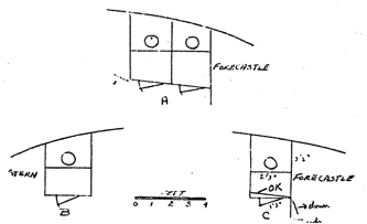
Two ladderways leading from the
main deck to the topgallant forecastle deck have been placed as close to the
water closets as possible and still allow the doors to open. The width of
companions has been assumed—2 feet.
The dimensions of the deck house
were given by the BDA as 41 feet long, 18 wide, 6½ high. According to
this report, one watch of the crew was accommodated here and the house also
contained the "galley and other apartments'", It has been assumed
that the watch was accommodated in the forward division of the house for three
reasons. 1) This location places them as near the quarters of the other watch
as possible. 2) It places them in closest proximity to the water closets in the
forecastle wings which this watch presumably had to use, as well as the other
watch. 3) It was the general convention in describing a ship to commence
forward, and the crew's quarters were the first accommodations mentioned in the
description of the house.
It has been assumed that two doors
were more probable than a single entrance to these quarters. Not only may the
sailors make a quicker exit in time of emergency, but the apartment is thereby
made more equal to the accommodations of the other watch where two entrances
have been assumed.
Three entrances would seem to be
overdoing it a bit, as well as using up valuable space. These doors could go either
in the forward wall or in the side walls. The side walls are favored, as near
the middle of the house as possible, since by this means all entrances would be
most widely separated, and therefore theoretically closer to everyone's
assigned station. These accommodations are assumed to have extended the entire
(18 feet) width of the house. Although the area under the forecastle was
approximately 450 square feet, the area actually occupied by the crew would
have measured nearer 370 square feet, after subtracting the space occupied by
the bowsprit and chains. If the watch accommodated in the house were to receive
the same floor area, the accommodation would have to be about 20 feet 7 inches
long, or roughly one half the length of the house. In this connection it is felt that the arrangement of doors
and windows shown on Boucher's model must be mentioned even though
justification or the source for this arrangement was not found. The after edge
of the forward door measures 18 feet 6 inches from the forward wall.
The galley is the next division
reported by the BDA. The Buttersworth painting is the only one which shows a
galley stack. Although this painting is generally inaccurate, it has been used
for locating the galley. The stack extends above the top of this deck house a
little aft the middle, which should be near one wall of the galley since it
'should be located directly over the stove. The galley of the Bald Eagle was 8 feet wide so it may be
assumed that in the Flying Cloud the
galley occupied only one-half the width of the deck house.
Peake57 states that
framing for the cooking range was similar to that for hatchways. A note in the
description of the Staffordshire is
of interest with respect to the galley fitting: "The galleys are laid with
bricks, and lined with copper and tin, and their cooking arrangements are of
the most approved patents." An examination of the patent records disclosed
no patent which would be applicable, indicating "patent" was used as
a generic rather than specific term. Wilson277 states that the
galleybed consisted of the work connected with fitting and fixing, including
the lead for the bed and tin for covering the beams and deck, and bolts to se
cure the galley to the deck.
Chapelle206 in his
drawings of the Joe Lane shows a galley range of the following proportions.
Figure 36 - Galley Range
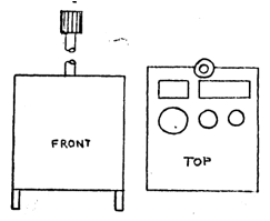
The nature of the "other
apartments" referred to in the BDA report had been determined by
comparison with similar ships. The other BDA reports indicate that the divisions
ranged all the way from a sail room to quarters for ten to twelve juveniles.
However, in the present case there is a limitation imposed by the space
remaining, there being only 380 square feet left after subtracting the crew's
quarters. Table 14 gives an idea of the apartments located in the deck houses
of the other ships. The packet ship Staffordshire
has been excluded because we felt it would be misleading.
Table 14 - Deck House Accommodations
Name Length
by Width Accommodations
Stag Hound 42
x 24 crew,
galley, storerooms, etc.
Flying Cloud 41
x 18½ crew,
galley, other apartments
Flying Fish 33
x 15 galley,
cook’s sleeping quarters,
sail-room,
store room, aft 10-12
boys,
and staterooms for petty
officers
Westward Ho 25
x 16 galley,
crew, other apartments
Bald Eagle 36
x 8 life
boat, galley, stateroom for
forward
officers (carpenter
boatswain)
Queen of the Seas 38
x 16 galley,
3 sate rooms for forward
officers,
long boat
Shooting Star 22
x 10 crew,
state rooms for boatswain
and
carpenter, galley
Don Quixote - galley,
sail room, store rooms,
quarters
for petty officers,
berths
for the boys
The BDA description of the deck
cabin of the Flying Fish seems to
have included all the accommodations (except the crew) commonly placed in this
house since the size of the house was (some 260 square feet) smaller
(two-thirds of the area assumed for crew accommodations) than on the Flying Cloud, it has been assumed that
essentially all these should have been present in the Flying Cloud.
The forward officers evidently
consisted of the boatswain, carpenter, and sailmaker. The cook may also have been considered a forward officer,
but he generally had a cabin by himself.
Two state rooms have been assumed for the carpenter and boatswain. The BDA seldom made mention of the
sailmaker and one was seldom listed in the crew lists. A cabin fitted for ten boys has been
located in the after part of the house.
Since both the Stag Hound and Flying Fish
had a store room (or rooms) contained in their deck houses, it is considered
justifiable to assume that the Flying
Cloud had a similar accommodation. Since the storeroom was undoubtedly for
food, it is reasonable to place it near the galley, either immediately abaft or
opposite it.
It is believed that the cook
occupied a private cabin within the deck house. The Flying Fish is stated to have had such an accommodation, and the
cooks of the Staffordshire were also
accommodated here. It has been assumed that the cook's quarters were
immediately abaft the galley. Figure 38 gives the deck house arrangement.
The BDA description of the Flying Cloud states that "Her poop
deck is the height of the main rail, 68 feet long, and is surrounded by an open
rail supported on turned stanchions. In the front of the poop is a small
portico, which protects the entrance to the cabins..." Since this affords
little basis for reconstruction, much of the following is based on the rather
complete description of the Stag Hound
given in the BDA. Therefore, it was necessary to reconstruct insofar as
possible, the after cabin of the Stag
Hound which was then used as a basis for the Flying Cloud reconstruction, (see Figure 39)
The BDA states that the half poop
deck of the Stag Hound was the height
of the main rail (about 5 feet 2 inches). The after cabins had a descent of 3
feet below the main deck, and were 6 feet 8 inches high. Figure 37 presents a
cross section of this cabin. ForbesN23 states "I have generally
held in that the most complete and safe arrangement for ships is to have a
half-poop about as high as the main rail, descending three or four steps into
the cabin." Since the main rail of the Flying
Cloud was only 5 feet high, a descent of 3 feet 2 inches below the main
deck with four steps, 9½ inches apart, has been assumed.
Figure 37 - Cross Section of Poop Deck Cabin
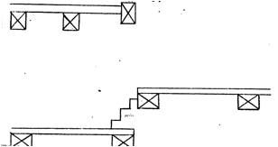
Portico The portico was used
to cover the stairs leading to the after cabins. There is no reason to make
this portico particularly large since it served only to cover and give head
room to these stairs. It has been assumed that this portico measured 8 feet
wide by 8 feet long, extending 2½ feet forward from the poop deck.
Figure 38 - Deck Cabin
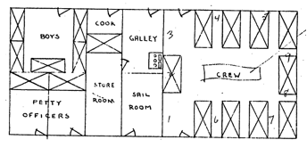
Figure 39 - Aft Cabins
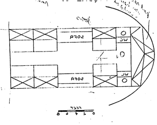
Forward Cabin It has been
assumed that the length of the 12 by 18 foot of the forward cabin of the Flying Cloud was 12 feet, since it was
the usual procedure to give the length of a cabin first then its width and a
cabin 18 feet long would have stuck out from under the poop deck 6 feet. It
could be argued that since the poop deck was longer than that of the Stag Hound, all cabins should also be
larger. However, on both ships this cabin has been assumed to have housed the
same personnel (captain, three mates, a steward) and the pantry. There is
therefore little reason to change the over-all size of the accommodations. It
seems reason able that this cabin would also contain a water closet for the use
of the officers as was described for the Witch
of the Wave and several other ships.
The Witch of the Wave also
gives the most complete description of the accommodations of this cabin, and it
was from here that the relative locations of the various state-rooms, etc. was
determined. The BDA description states
She has three cabins,
the first contains the captain's state-room on the starboard side, which
overlooks that side of the main deck, and near it is a stateroom for the
steward. Abaft these, on the same
side, is the pantry. On the
opposite side, are staterooms for the officers and a water closet.
The Queen of the SeasBDA had
before the cabin is a vestibule 12 feet - square, with the staircase in it, and
on the starboard side of it is the pantry close abaft which is the captain's
state room. On the opposite side is a mess room for the officers, and before it
the stewards room.
Assuming a 2 foot passageway
amidship all the Queen of the Seas
apartments would be 5 feet deep. Assuming a 5 foot width for the pantry and
steward's stateroom the captain's room and officer's mess would be 7 feet
wide. Figure 40 presents the
arrangements of the forward cabin of the Flying
Cloud.
Figure 40 - Forward Cabin
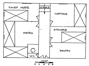
The doors to the forward cabin may
be either on the forward side of the portico or on the sides. Because of the
size which has been chosen for the portico, and the more economical utilization
of space, it has been assumed that the doors were on the forward side. These
doors may either be flush with the main deck, or they may be at the bottom of
the four steps. In the latter case they would have to open inward. If there
were two doors, each 1¼ feet wide there would still be clearance to get
out of the first two cabins. A single door hinged on either side would also
give ample clearance. Doors on the main deck level would offer no difficulties.
It is thought that such doors would open out since if they opened inward they
would be awkward to close from outside. It has been assumed that doors were
fitted on the main deck level only.
Great Cabin Although the Stag Hound has a cabin in the same
general location as the great cabin in the Flying
Cloud it was not entirely comparable. The forward portion of the great
cabin shown in Figure 38 is equivalent to the Flying Cloud's great cabin. The after division of this cabin in the
Stag Hound, is comparable to the Flying Cloud's after cabin.
Since the combined lengthBDA
of the two after cabins of the Stag Hound
was exactly the same as the length specified for the poop deck, it may be
assumed that in this case the after cabin extended to the stern. Since the poop deck of the Flying Cloud was 24 feet longer than
that of the Stag Hound, it might seem
correct to increase the number of passenger accommodations proportionately.
However, if the same size staterooms are added to the great cabin until its
length is commensurate with the length of the poop deck, there would be a total
of 16 staterooms for the passengers. Table 15 gives the estimated number of
passenger staterooms in the early McKay clippers. It will be noticed that none
of them approached as many as 16 staterooms, and there is no reason to expect
the Flying Cloud to have been an
exception.
Table 15 – Stateroom Passenger Accommodations
Stag Hound 7
Flying Fish 6
Westward Ho 9
Bald Eagle 5
Thus, the great cabin of the Flying Cloud probably had the same
number of staterooms as the Stag Hound.
The size of each stateroom may seem
unbelievably small, but the following are descriptions which provide sufficient
information for estimating the size of the staterooms.
Stag
Hound: "The after cabin is 32 feet long by 13 wide. Its after
division is fitted into a spacious state-room with two berths, and is admirably
adopted for the accommodation of a family. Before this there is a water closet
on each side, then a stateroom; before that a recess of 8 feet on each side,
and then two staterooms." If the water closets are 3 feet wide; the average
width of staterooms is 5¼ feet. If a passage way of 3 feet is assumed,
the stateroom depth would be 5 feet.
Queen
of the Seas: "'The forward cabin is 24 by 12 feet and contains 4
staterooms on each side with 4 berths in each.” With a 2 foot passageway
amidships this gives staterooms 6 feet wide by 5 feet deep. "Her after
cabin is 31 feet long, 12 feet wide and contains 10 spacious staterooms and
other apartments (probably includes 2 water closets). A splendid sofa spans the
stern, and a large mahogany table, with settees on each side extends through
its center." It seems that at least a 4 foot passageway must be allowed
amidships to accommodate the table and settees, leaving a cabin depth of only 4
feet. If it is assumed that the sofa and a water closet on each side took up 3
feet fore and aft the staterooms would be 5 feet 5 inches wide.
Hoogly:
"Her staterooms are mostly very large, 9 by 7½ feet . . ."
James
Baines: "The ladies cabin is aft, and is 30 feet long by 13 wide
and 6½ high. Aft is a beautiful sofa, fitted to correspond with the
curve of the stem, and over it is a neat bookcase. The forward partition is
ornamented with a large plate glass mirror, which gives a reflected view of the
cabin abaft it. The Captain's cabin and sleeping room are on the starboard side
and communicate with the wheel house on deck, so that it will not be necessary
to enter the ladies cabin. Besides these, the cabin contains eleven spacious
staterooms, a bathroom, and other useful apartments." With a 3 foot passageway
the length of the cabin, the staterooms would be 5 feet deep. Assuming that the
captain's rooms equaled one and one-half staterooms, and there were two water
closets together equal to one-half a stateroom, each stateroom would be4 feet 7
inches wide.
From the foregoing it would appear
that a single stateroom (2 berths) averaged 5 feet deep by 5¼ feet wide,
while a double stateroom (4 berths) averaged 5 feet deep by 6 feet wide. In the
single stateroom the berths would be along the outside of the ship as noted by
ForbesC8. In the double stateroom they could be along both sides of
the cabin. Bunks measuring 5¼ by 2½ feet have been assumed.
Both the Stag Hound and Flying Fish
had recesses along the side (for sofas) and it has been assumed that the Flying Cloud was similarly fitted. In fact, it has been assumed that the
forward two cabins of the Flying Cloud
and Stag Hound were virtually
identical. It has been assumed that there was a 3 foot passageway amidships in
the Stag Hound, and Flying Cloud.
After Cabin The most logical
arrangement to assume for the after cabin of the Flying Cloud would be one similar to the after division of the
after cabin of the Stag Hound. The
basic assumption has been made that in this case "apartment" is
synonymous with "state-room". A number of possible arrangements for
the after cabin are shown in Figure 41.
Figure 41 - State Room Arrangements
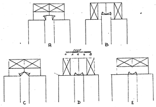
Arrangement D and E would probably
not have been termed a separate cabin, but rather simply the after staterooms
of the main cabin. Of the other three arrangements, C seems to offer the most
economical use of space and best door arrangement.
Figure 42 presents the plan of the Flying Cloud's after cabins which has
been accepted.
Figure 42 - Flying
Cloud After Cabins
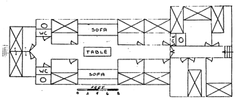
The upper part of the deck house of
the Stag Hound was "ornamental
with panels", while the Staffordshire
had her deck house "finely ornamented with paneling, venetian blinds,
etc." It has been assumed that the deck house of the Flying Cloud was likewise ornamented with panels. The ships of this period were fitted
out in all the Victorian splendor that can be imagined. The most complete
description of this fancy work found was in the BDA report of the Staffordshire. Although being a packet
ship it might seem to have minor bearing on the question of ornamental work
aboard the Flying Cloud, it has been
included to give an idea of the types of finishing then in style and considered
in good taste or, as MacLean said in the description of the Westward Ho, in "the best style of
art". The framework of the Staffordshire's
great cabin
... is of mahogany. The panels are crowned
with gothic arches, and are of pure enameled white, lined along the margins
with gold, and flowered with gold in the-centers. They are raised, or rather
their outlines are indented and form rosewood grooves, outside of which are the
pilasters. These last are also lined with gilding, and ornamented with gilded
carved work in the middle. Their capitals are richly carved and gilded, and
their pedestals are enameled in imitation of dark veined marble. The forward
partition amidships displays three mirrors, arched like the panels; and aft
there is a splendid sofa, close to the stern. The rudder casing is finished in
the same splendid style as the sides of the cabin. The beams are fringed with
gilding, and the cornices are of paper mache, ornamented with roses, blooming
in gold. The ceiling is white and the lofty skylights and stern-lights are at
once ornamental as well as useful.
The carpets, table, settees, and other
furniture, are of the richest material suitable for sea service, and are
elegantly arranged. Its staterooms
are spacious...and are furnished in the same style of elegance as the cabin... The cabins were designed and furnished
by Mr. Manson; and her ornamental carving by Messrs. Gleason & Sons.
Nothing has been mentioned
concerning the ornaments of the Flying
Cloud. The Stag Hound had her
forward cabin was "neatly painted and grained” and the one on the Flying Fish was “neatly painted and
ornamented.” It has been assumed that he Flying
Cloud was finished similar to the Stag
Hound. Most forward cabins had
windows of stained glass, sheltered with venetian blinds, and this arrangement
has been accepted for the Flying Cloud.
The BDA gives a rather complete
description of the Flying Cloud's
great cabin. "The . . . great cabin, is beautifully wainscotted with satin
wood, mahogany and rose wood, set off with enameled pilasters, cornices gilt work,
etc. The panels are of satin wood, gothic in their form, and are set in
mahogany frames edged with rose wood." The arrangement for fancy work on
the Flying Cloud has been determined
by comparing the descriptions given for the Staffordshire
(above) and for the Stag Hound
"The sides of the (after) cabin are splendidly finished with mahogany
Gothic panels, enameled pilasters and cornices, and gilded moldings, (see
Figure 43).
Figure 43 - Stag
Hound After Cabin
Although the cabins of the Staffordshire were designed and
furnished by Mr. Thomas Manson, McLean tells us in the description of the James
Baines that Messrs. Jas. H. Beal and Brother furnished '"nearly all of the
splendid ships which have been built by Mr. McKay." Cabin furnishings
consisted of the carpets, tables, settees, sofas, mirrors, etc. The BDA
description of the Shooting Star
gives an idea of the furnishings of the period:
The transom is fitted as a sofa covered with
crimson damask, and near it is a circular divan, with a central pyramid, on the
front of which is a circular mirror set in a gilded frame. The divan is also
covered with crimson damask. A mahogany table and seats occupy the center of
the cabin. The after part of the cabin, when required can be converted into a
separate apartment by curtains.
The Witch of the Wave had her "transom...fitted as a semi-circular
sofa, covered with rich velvet." Mahogany was probably used throughout. It
is stated in the BDA description of the Staffordshire
that her staterooms were "furnished in the same style of elegance as the
cabin." It has been assumed that the cabin and staterooms of the Flying Cloud were furnished similar to
the descriptions above.
The Great RepublicS10 had her tables furnished with
"plate, Ec by Mr. Samuel T. Crosby, the most eminent in his line of
business in Boston." It is not unlikely that Mr. Crosby also furnished
plate for the Flying Cloud.
An attempt has been made here to
cover only the most important and obvious of the numerous fittings aboard any
ship.
Material The Chariot of Fame plan shows the rudder
colored the same as the keel, frame, etc; therefore, white oak has been assumed
as the material of construction.
Size The MIT and Wall lines
do not show a rudder, but the sail plan on the MIT plan shows the portion of
the rudder above the load water line.
Using this as a basis the rest of the rudder has been proportioned to
con form to that shown on the Chariot of
Fame plan. It has been assumed that the rudder was as thick as the
sternpost of 16 inches. Griffiths shows a diagram in which the rudder is 13
inches thick with a 16 inch post, but others (Curtis21, PeakeP1.9,
and ThearlP.LXXXIII show the rudder and post sidings equal. A 16
inch rudder head is shown on the Chariot
of Fame plan. The Chatsworth had
a-rudder stock 17 inches in diameter with a stern post sided 17 inches. Since
the rudder has been assumed 16 inches thick, the rudder head of the Flying Cloud has also been set at 16
inches.
Construction The
construction details of the rudder shown on the Chariot of Fame plan have been adopted for the Flying Cloud, (see Figure 44).
Figure 44 - Rudder
Thearl249 states that
the rudder was dowelled and bolted together, but since dowelling was more an English
practice, seldom mentioned in American literature, it has been assumed that
bolts were used as fastenings. Copper bolts, 1½ inch in diameter,
passing through all timbers have been assumed since these timbers were of the
same siding as the keel and keelson timbers.
Gulleting These were small
pieces of wood running between the pintles. They are assumed to have been fastened by boat spikes
similar to the false keel since they were not structural members.
Hoops Griffiths implies that
rudder heads were sometimes banded with iron when he states that a bar of iron
should be three times its thickness longer than the circumference of the spar
or rudder to be banded. How ever, neither the Chariot of Fame nor the Great
Republic plans show a banded rudder head and none has been assumed for the Flying Cloud.
Pintles & Gudgeons Brady255
mentions iron pintles while Fmcham12 says pintles were made of mixed
metal; but these are blue on the Chariot
of Fame plan, the same as the other iron work shown. Iron has been as sumed
for the Flying Cloud. Pintles and
gudgeons have been arranged ac cording to the Chariot of Fame plan as to location and size. The scraps shown are
3 inches wide and extend to within three or four inches of the after part of
the rudder. Fastenings have arbitrarily been assumed as 1 inch iron, driven
through and clinched. Wilson250 states that braces and pintles were
cast with straps, which were let into the sides and through bolted. Butts60
claims that pintles should be two times the rudder diameter in eighths or 4
inches in diameter which has been assumed.
It is generally agreed that the rudder should be able to move
42° to -45° from a fore and aft line. Wilson250 states that the
rudder was bearded to 38° while the stern post was bearded so that the rudder
would swing to 42°.
Woodlock It is generally
agreed (Peake143, Thearl250, and Wilson250)
that a woodlock, a small piece of wood which prevents the rudder from being
unhung, was nailed to the rudder under the upper pintle. Wilson250
states that it was made of oak, coppered before being put on, and secured in
place by a copper bolt driven through cornerwise into the stock of the rudder
so that it can be readily drifted out when the rudder is required to be
unshipped.
Cleat Luce92
states sometimes a strong cleat was placed under the second gudgeon on which
the pintle partly rested. Wilson250 states that a metal step called
a saucer was secured to the stern post below the center brace to keep the
straps of the pintles and braces apart.
Rudder Chains Rudder chains
were used to prevent the*loss of the rudder and to provide means of control if
the wheel became inoperable. Peske143
states that there was usually a bolt driven in the back of the rudder just
above the water to which short chains were shackled which in turn were
connected to the stern and thence to the quarters by rope pendants. ThearleP1.LXXXIT
shows a strap fitted for this purpose. Although the Chariot of Fame and Great
Republic plans show no indication of such fittings, it has been assumed that
the Flying Cloud was fitted with
chains in the manner described by Peake. No chains were observable in the
Currier lithograph or in the Chinese painting. Magoun118 claims that
the Flying Cloud had only one rudder
chain, but gives no source for this apparently unusual arrangement.
No mention is made in the BDA
report of the Flying Cloud concerning
boats. The Flying Fish was reported
to carry five boats, as was the Challenge.
The only description of boats given by the BDA during 1851 was for the Challenge as follows:
She has five boats, the first a launch 26
feet long, 9 wide and 3½ deep, double planked and modeled for sailing or
rowing, having a jib and "mainsail, and rowlocks for 12 oars.. The next
are two cutters, carber built, 27 feet long, 7 wide, and 2 feet 9 inches deep,
also fitted for sailing and rowing; each having the same number of oars as the
launch. The third cutter is 25 feet long, 5 feet 5 inches wide, and 2 feet 4
inches deep, to be rowed by five oars. The captain's gig is 30 feet long, 5
wide, 3 feet 3 inches deep, is clincher built, to be rowed with six oars. These boats are all built of white oak
and cedar, are copper fastened, have brass rowlocks, and are furnished with
sails, awnings, water breakers, etc.
There is little uniformity
exhibited among the ships which had boats mentioned in the BDA, either as to
their number, location, type, or size.
According to the BDA, the Antelope
had two boats, the Polar Star had
three, The Golden Eagle, Golden Light, Golden West, J. Montgomery,
Whirlwind, Winchester, and the Santa
Claus had four, and the Ellen Fester,
Flying Childers, Queen of the Seas, Challenge,
and Flying Fish all carried five
boats. The Currier lithograph of the Flying
Cloud shows two boats on iron quarter davits, and at least one boat on the
deck house. The Chinese painting shows a starboard quarter boat on iron davits
and may also show one on the port side. The woodcut of the Flying Cloud loading at New York shows one quarter boat on the
starboard side (but aft of the mizzen rigging) while the top of the deck house
is not shown. Other paintings show a various number of boats on the deck house
and on the quarters. It has been assumed that the Flying Cloud carried four boats, two at the davits and two on the
deck house placed bottom up. The length of the quarter boats shown on the
Currier lithograph is 27.5 feet while the one boat visible on top of the deck
house is 34.6 feet long; the Chinese painting shows a 28.5 foot boat on the
starboard quarter davits. There is a close similarity between the measured
length of quarter boats of the Flying
Cloud and the length of the two cutters of the Challenge described. There is also similarity between the
dimensions of the 27 foot cutter of the Challenge
and the 26 and 28 foot cutters presented in the Navy specifications and plans
bock of 1900 (see Figure 45). It has been assumed that the shape of the 28 foot
Navy cutter (which is the same as the 26 foot cutter) is valid for the two
quarter boats of the Flying Cloud.
Figures 46 and 47 show the lines and sail plan of this boat.
The BDA cites many instances when
the ship's long boat was stowed on the deck house, and it has been assumed that
this is the boat shown in the Currier lithograph. Although the Challenge had a 26 foot launch and a 30
foot captain's gig, it has been assumed that the Flying Cloud had only a 30 foot long boat. Since the launch of the Challenge and the launches shown in the
Navy specifications have similar dimensions, the lines of the 30 foot Navy
launch have been adopted for the long boat of the Flying Cloud, It has been assumed that the other boat on the deck
house was a slightly smaller cutter than those hanging on the davits; a 26 foot
boat has been assumed. Although
the dimensions of the smaller cutter of the Challenge
did not correspond well with the Navy specifications (see Figure 45). The Navy
lines and sail plan have been assumed (see Figures 48 and 49). It has been
assumed that these boats were fitted as were the corresponding boats on the Challenge.
Figure 45 - Principal Dimensions of Launches &
Cutters
Figure 46 - Lines of a 28 foot Cutter
Figure 47 - Sail Plan of 28 Foot Cutter
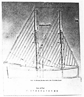
Figure 48 - Sail Plan of 30 Foot Launch
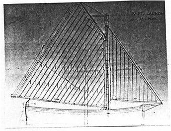
Figure 49 - Lines of 30 Foot Launch
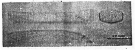
Davits The location of the
davits has been determined from the Chinese painting as being 17 inches from
the bow and 29 inches from the stern of the boats, an average of 23 inches. The
davits are shown 5 feet h inches above the monkey rail with the keel of the
boat being even with this rail. The after davit is shown only a few inches
before the forward mizzen mast shroud.
Anchors The weights of
anchors specified by Brady328 for launches and cutters used on war
ships have been used as the basis for determining the size of anchors in each
of the boats for the Flying Cloud.
The comparison has been made on the basis of the product of the three major
dimensions of the boats. One anchor weighing 100 pounds, two weighing 60
pounds, and one weighing 50 pounds have been assumed.
Figure 50 - Size of Anchors for Launches and Cutters
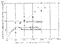
Butts60 gives the length
of double oars as a proportion of the boat's breadth as follows:
Launch
1.25 2d
Cutter l.40
1st
Cutter 1.30 3d
Cutter 1.45
The BDA makes no mention of the
ground tackle of the Flying Cloud. An anchor approximately 8½ feet
long, exclusive of an 18 inch ring, with the arm passing through 6½ feet
above the crown is shown on the Chinese painting of the Flying Cloud. Only two descriptions of ground tackle of any
specific ship have been found; the BDA description of the Challenge, and the description of the Great Republic.S20 Since the Great Republic had Porter's patent anchors, the weights given for
these are no help. [Ed. Porter patent U.S. 2,497] The total weight of the three
anchors of the Challenge was
reportedly of 13,378 pounds, besides a stream anchor and chain. According to
Brady290 and Fincham4 a ship that had a total of three
anchors and a stream anchor would have had two bowers and one sheet anchor, all
of the same weight.
By using one formula given by Luce268,
which states that the anchor weight (exclusive of stock but inclusive of
bending shackle) equals three times the square of the extreme breadth of the
ship, a weight of 5,043 pounds is obtained. Using a second formula supplied by
Luce268 which states that the anchor weight equals two thirds the
drought plus the beam, the whole times 100, one gets 4,433 pounds. For three
equal size anchors, the above formulas give a maximum total weight of 15,129
and a minimum of 13,299 pounds, which bracket the 13,378 given in the BDA.
Since the second rule gives such a close approximation (-0.6%) to the BDA
value, this rule has been used in calculating the size of the anchors for the Flying Cloud, giving 4,144 pounds as the
weight of the bowers and sheet anchors. It should be pointed out that this
weight is some 10% below that necessary to "equal or exceed the
requirements of Lloyds in weight and length" as given by Butts84
(see Table 16). However, since the ground tackle of the ChallengeBDA and the details connected therewith have
been made to surpass the strictest requirements of Lloyds", it has been
assumed that the weights derived above are applicable.
Table 16 - Lloyds Regulation for Ground Tackle
Ship Chain Length Wood Number
Stocket of
Anchors
Anchors
(Tons) (Inches) (Fathoms) (cwt)
Bowers Stream Kedge
1200 2 to 1 ⅞ 300 40 3 1 3
1500 2 300 45 3 1 3
2000 2 ⅛ to 2 ¼ 300 50 3 1 3
According to Brady328
with bowers of 4,144 pounds, the stream anchor should weigh 1,056 pounds or
nominally 1,000 pounds. Luce270 also states the stream anchor
weighed about one-fourth of the weight of the bower. Figure 51 presents this relationship graphically as given by
Brady328.
Figure 51 - Weight of Anchors
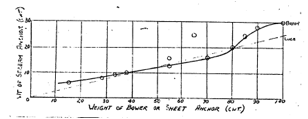
Chains The BDA states that
the Challenge had two chains 120
fathoms in length, one 1 ⅞
inches and the other 2 inches, to go with the three bowers weighing 4,460
pounds and the stream anchor weighing 1,116 pounds. The BDA reported the Phantom
(1,300 tons) had four chains of 1 ⅞,
1 ⅝, 1 ⅜, and 1 inch; and five
anchors weighing 4200, 3700, 3200, 1200, and 500 pounds. Figure 52 plots the
size of these chains against the weight of the anchors. It also gives the chain
sizes acceptable to Lloyds as given by Butts84 and the size of chain
recommended by Luce281 and Brady328.
Figure 52 - Chain Size vs Anchor Weight
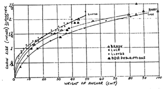
Two ⅛
inch chains for the bower and sheet anchors and one 1 inch chain for the stream
anchor, each 120 fathoms long have been assumed for the Flying Cloud. It was often stated in the BDA reports that the
ground tackle chains exceeded the requirements of Lloyds in length. Although
Table 16 indicates that 300 fathoms was required by Lloyds, it has been assumed
that since the Challenge had only two
120 fathom chains, the same length would be acceptable in the Flying Cloud. Luce281 states
that chain cables were shackled every 15 fathoms, with the rounded part of the
shackle forward, and at certain intervals in the chain were placed swivels.
Size Davis, in "The Built-up Ship Model" suggests a
method of estimating the size of an anchor from its weight. He assumes that the
metal coming off the flukes will make the palms and the iron taken from the top
of the shank will be made up by metal added at the crown. Using his method the
shank length comes out 6.7 feet, not particularly close to the 8 foot anchor
shown on the Chinese painting. This anchor would require a 10 inch square
shank. Porter presented a diagram showing the length of the arm of common
anchors of different weights. An anchor of 40 cwt had an arm 4 feet 2½
inches long and an anchor of 45 cwt had a 4 foot 4½ inch arm.
Stock No description of the
exact shape of anchors has been found.
Fincham4 states that the length of the wooden stock was equal
to the length of the shank plus one-half the diameter of the ring. The middle
dimension of the stock was one-twelfth its length, while the end dimension was
one-half of this. Stocks were made from two pieces, separated at the middle by
½ to 1¼ inches, a 3 inch wide chock (wedge) placed between them,
and fastened with 4 bolts placed at half the largest size on each side of the
middle, and a quarter from the edge; three or four treenails were placed at
equal distances, and two hoops evenly distributed on each side, if the anchor
was under 4,000 pounds, three to all anchors above 4,000 pounds. According to
Luce270 an oak stock weighed about one-fourth as much as the anchor
and it was kept coated with coal-tar, not paint. If it is assumed the shank was
only as long as the length of two arms combined and the cross section is
calculated for a total length of 17 feet (4 x 4 feet 3 inches), 8⅞ inch square material would
be required and the shank length would be 8½ feet. The stock was made
straight on the part towards the ring, but the other way it was tapered equally
on both sides and double on the bottom. DavisDp118 adds that the
stock is parallel for nearly one-half its length.
Shank and Arms Davis and
Luce270 state that the length of the arms or flukes from the throat
to the bill was equal to the length of the large part of the shank from the
crown to the top of the stock, and the palm was equal to one-half the length of
the arm or fluke from the nib-end to the stock, while it was as wide as it was
long; its width was rounded to a point at the nib. The shank tapered from the
crown to the stock, being one-third smaller, just below the stock where the
chamfered edges of the shank end in a square (this is called the small round of
the stock). Luce272 states that the average proportion in use were:
shank 100; ear arm from crown to bell 40; stock 100; radius outside 35; angle
of face of palm with shank 51°; when on ground angle of shank 24°; blade 75°.
Porter51 gives a drawing of the fluke of a common anchor which is
reproduced as Figure 53.
Figure 53 - Fluke of Common Anchor
Figure 54 gives the proportions of an anchor shown by DavisDp
and of Cotsell's admiralty anchor.
Figure 54 - Anchors
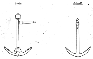
Location DavisDp118
states that the bowers were stowed on the bows, one on each side. Captain
Winsor's account of a typhoon (August 8, 1860 — China Sea) indicates
that, at least at this time, an anchor was carried on the bow lashed to a ring
bolt, "The starboard anchor washed off of the bow. Tore out all the
ringbolt and everything it was lashed to." Leslie270 claims the
bowers were stowed just abaft the cathead, in the bows of the ship, while the
sheet-anchor, which was used only if both bowers were lost, was stowed abaft
the foremast, near where the fore sheet passed into the ship. Davis says the
sheet anchors were stowed just abaft the fore channels, while Luce274
states this anchor was stowed in the main hatch. DavisDp claims the
stream anchor was a spare one kept stowed on end in the main hatch lashed to
the stanchions. Fincham3
states that the stream anchor is used only to ride in rivers or to bring up for
a short time.
Number The BDA reports that
the following ships were fitted with two capstans; the Stag Hound, Flying Fish, Westward Ho, Bald Eagle, and many other clippers. Although the BDA makes no
mention of capstans on the Flying Cloud
and reports that the packet ship Staffordshire
had three capstans, there is considerable justification for assuming that the Flying Cloud had only two capstans.
However, this is not the conclusion reached by Magoun and Boucher who both show
four capstans. It is not known what justification was found for these
additional capstans, but until something is found which contradicts only two
capstans, this number must be accepted.
Materials The capstans were
very probably made of mahogany and locust, since out of the one ship launched
in 1850 and the seven ships launched in 1851 which had capstans described in
BDA reports, five were of mahogany and locust and two were of mahogany alone
(see Table 17). The use of brass and composition in capstans is somewhat questionable.
Two of the above capstans were described as being inlaid with brass; one was
inlaid with compositions; four were "brass mounted"; and one had
"composition circles and pawls'". It seems likely that all actually were brass or composition
mounted and that some of the earlier ones were inlaid. Since the launching date
of the Flying Cloud falls at the very
end of the "inlaid" series, it has been assumed that the capstans
were inlaid with brass. It is also likely that brass drum heads were common to
all, although this is not evident from the descriptions. Table 17 lists, in the
order of launching, the ships which had capstans described in the BDA in 1850
and 1851.
Table 17 - Capstan Material
Ships Where
BDA Wood
Remarks
Built Date Used*
1850
Stag Hound Boston Dec. m
& l inlaid
with brass
1851
John Bertram Boston Jan. m&
l composition
circles
and
pails & brass heads
Shooting Star Boston March m
& l inlaid
with brass
Mermaid Boston April l
& m inlaid
with composition
Witch of the Wave Boston May
brass
heads
Challenge New York June brass
heads
Staffordshire Boston July m brass
mounted
R B Forbes Boston Sept. m
& l brass
mounted
Samuel Lawrence
Boston Sept. l
& m brass
mounted
Antelope Boston Nov. m brass
mounted
*
m- mahogany l - locust
Construction It has been
assumed that the type of capstan used aboard the Flying Cloud was the double capstan shown in the plans of the Great Republic. Wilson248 states that there
was a wrought iron spindle which had the framing of two decks to steady it. It
turned in a bush or collar in the upper of these decks, and had the pivot at
its lower end supported by a step fixed to the lower deck. The greatest diameter of the spindle
was about the middle, and ranged from 5-8 inches. The diameter at the ends was
two thirds that of the middle. The drum head of the capstan ranged from 3 to 5
feet in diameter with bar holes 3 to 5 inches square and 10 to 12 inches
tapering inwards. Capstan bars were 8 to 14 feet long, connected together
through their outer ends connected together by a rope called a swifter. Capstan
bar holes were spaced about one foot apart.
Location One of the capstans
was unquestionably on the forecastle, probably amidships, but the fore and aft
position can only be surmised from a study of various paintings, particularly
the Currier lithograph. It has been assumed that the capstan was located 15
feet from the bow. When specified in the BDA reports, the second capstan was
located on the quarter deck. The location of this capstan on the Challenge was given as:
mainmast-hatchway-capstan-hatchway-mizzenmast, and the R. B. Forbes had her
capstan abaft the mainmast before the hatchway. It has been assumed that the
capstan on the Flying Cloud was
between the after hatchway and the poop deck.
Type By the time of the clippers,
the use of Reed's patent steering apparatus seems to have gained complete
acceptance on McKay's ships. All BDA descriptions of McKay ships which mention
the steering apparatus by name refer to Reed's type, and although not so
stated, it may be confidently assumed that the Flying Cloud used this type of apparatus. The best sources of
detailed information are the original patents issued to Reed which give all
details (U. S. Patent Nos. 5,242 and 6,507). The BDA report of the Don Quixote (October 27, 1853) stated
that she had Reed's steering apparatus with an iron yoke brace on the after
part of the rudder head to keep the rudder pintles on their centers. This seems to be discussed as something
new or out-of-the-ordinary and it has been assumed that none was fitted on the Flying Cloud. However, it has been
assumed that all improvements patented up to 1851 were employed; therefore
Patent 6,507 has been assumed valid.
Construction The location of
the steering wheel is relatively fixed since there was a direct vertical
connection with the rudder head. Wilson255 states that steering
wheels range from 3 to 6 feet in diameter. The barrel, rim, and standards of
the wheel were made of mahogany and the spokes of locust; the shaft was of
copper or composition. The wheel was arranged so that the lower rim of the
wheel moved opposite to the movement of the rudder. It is thought that the Flying Cloud would have had a fairly
large wheel; a 6 feet diameter has been assumed. The other specifications given
by Wilson255 have also been assumed, with the added feature of an
embossed emblem (usually a star) fixed to the upper-most spoke with the rudder
amidships placed as an night time aid to the helmsman.
Size The Chinese painting
shows a wheelhouse 8 feet 10 inches long, the height of the underside of the
monkey rail aft and 1 foot 4½ inches higher than this forward; the wheel
is not actually visible, but it is probable that this is what causes the
forward part of the house to look sloped. In this case the wheel would have a
diameter of approximately 6 feet 6 inches to 6 feet 10 inches. Since the same
type of house is fitted on the MIT model of the Invincible the above dimensions
have been assumed valid. A width of 7 feet 5 inches has been assumed since this
is approximately in the same proportion as shown on the Invincible.
Type No mention is made of
the pumps of the Flying Cloud. However,
the BDA states that the Stag Hound
had "patent copper pumps, which work with fly wheel and winches". The
BDA description of the John Bertram
indicates that these were probably of "New York patent." The Flying Fish and Westward Ho had Litchfield's patent pumps according to the BDA,
while the description of the Stag Hound's
pumps indicate that they were also of Litchfield's patent. Although no U.
S. patent was found under
Litchfield's name, it is known that C. L. Litchfield was from New York.
According to the BDA of July 5, 1852, Litchfield's pumps were sold by Whiton,
Train & Co., ship chandlers located at 1 City Wharf. Since it is reasonable
to assume that the Flying Cloud was
fitted with pumps in a manner similar to the above ships, it has been assumed
that the Flying Cloud had
Litchfield's patent pumps. Figure 55 shows the fly-wheel pumps which Magoun128
believes were aboard the Flying Cloud.
Figure 55 - Fly Wheel Pump
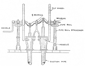
Number Various BDA reports
indicate that in many ships there were "two hold pumps and two bilge
pumps". These were specified for the Polar
Star, Samuel Lawrence, Orient, J. Montgomery, and the West
Wind. It appears that the hold pumps were of Litchfield's patent, and may
also have been used for the bilge pumps.
Location The location of the
hold pumps in many ships was abaft the main mast, inside the fife rail, a
location which ForbesN25 acknowledges by saying "as to the
position of pumps, the one generally chosen is the worst, or nearly so that can
be selected; they are, in ninety-nine cases in the hundred, placed very near
the mainmast; and it is certainly a convenience to put the pumps into the same
'thick-work' around the mainmast, it makes a good finish, looks well,
accommodates the capstan..." This location for the pumps has been assumed
for the Flying Cloud.
Other Pumps A Flander's
patent force pump was often mentioned by the BDA. This pump was fitted aft and was designed for wetting sails,
washing decks, and extinguishing fires "should such a calamity befall
her". It is probable that the Flying
Cloud carried such a pump, but the location is not known. No record of a U.
S. Patent was found. [Ed. U.S. patent 8,239]
Type It seems justified on
the basis of the BDA reports to assume that the Flying Cloud had a patent windlass since the Stag Hound and Flying Fish
were stated to have had one. The only clue as to the type is given in the
description of the Stag Hound, where
it was stated that her patent windlass had mends which ungear". The
patented windlasses in existence at that time were examined (U.S. Patent Nos. 2449, 3291, 5477). However,
none of these patents seem to fall under the above description, at least none
seems to make a point of "ends which ungear". The Chariot of Fame plan shows a windlass,
and the proportions shown there have been assumed valid for the Flying Cloud. Handles similar to those
shown in Patent 2449 and a ratchet similar to that shown in Patent 3291 have
been assumed. Figure 56 gives the shape of the windlass shown by Magoun:
Figure 56 - Windless
Location The usual location
for the windlass was under or lust abaft the break of the topgallant
forecastle. It has been assumed that in the Flying
Cloud it was located just aft the break. The accompanying bitts have been
placed in the proper location to support the windlass.
Fincham defines the binnacle as a
case to contain the compass, lights.
etc., but the shape and
exact form of this fitting is open to question. The BDA description of
the Queen of the Seas stated that her
--
binnacle is in the after part of an octagonal skylight, over
the cabin, and therefore at night its light will not be liable to be blown out
by squalls; but though this is excellent, the officer of the deck will have to
obtain a light for his pipe elsewhere (sailors prefer pipe smoking to cigars)
therefore, against this high handed outrage upon salt water rights, we enter
our solemn protest.
Thus it may be assumed that this
was not the usual arrangement for a binnacle. The only other BDA description for the binnacle was that of
the Staffordshire which had “mahogany
binnacles inlaid with brass”. Since no patented binnacle was found until 1865,
this is not a possible source of drawings. The only source is contemporary
models. MIT has on exhibit a contemporary model of Webb's clipper Invincible (1851) which shows a round
binnacle. A round binnacle as been
assumed valid for the Flying cloud. Wilson232 sates that all
fastenings within an 8 foot radius of the binnacle were of copper or
composition.
Water casks were generally round,
made of wood, and stowed along side of the deck house. The two exceptions to
this arrangement noted during p the course of this study were the Sierra NevadaBDA which “on
deck, along the sides of the house, she has square iron water tanks hold more
water and stow snugger" and the WebesterBDA
which had “water casks which stow on deck are not round but nearly square and
are fitted to stow along side of the house.'" Four round water casks were
shown on the Boucher model and on Magoun's plan of the Flying Cloud, two on each side of the forward part of the deck
house. This arrangement has been assumed for a lack of better information.
Clark42 stated that all
packet ships carried a white light at the bowsprit cap from sunset to sunrise.
These ships also carried a flare-up which was kept in the companion, ready for
immediate use. Longfellow’s poem “The Building of the Ship” confirms the
location of a light around the bowsprit by saying,
Twill be seen (the figurehead) by
the rays of the signal light
No evidence of side lights was
found on any of the contemporary paintings, therefore, it has been assumed that
none were fitted on the Flying Cloud. Magoun118 confirms that such
lights were not in use in 1851.
The government regulations were not checked in this respect; however
they would have little actual value in determining when a custom originated
since laws would be enacted only after a custom had proved valid.
Hold Emerson's patents (U.S.
Patent Nos. 5182, 5183) give a very complete outline of the construction of
hold ventilators described in the BDA report of the Flying Cloud. Emerson's patent No. 5842 showed the placement of ventilators
in a ship, but specified only that they be placed at the extremities of the
ship. The BDA states that the Witchcraft (two decks) had two of
Emerson's ventilators forward and one upon the quarter deck, the last of
polished brass. One of those drew
a column of air up from the bottom of the hold, through a flue of 10 inches in
diameter, and the other an equal column from the between decks, while that upon
the quarter deck blew a column down into the between decks. The Morning Light (three decks) had three
Emerson ventilators forward and two-aft which communicated with all the decks
and the hold. Although the BDA report of the Flying Cloud states only that she had person's ventilators
"for the purification of the hold", BDA reports of other ships
indicate that the arrangement of the Witchcraft
was typical.
The BDA of July 5, 1852, states
that Lewis Jones & Son at 36 Union St. had the exclusive patent rights of
these ventilators in Boston at this time.
Other The BDA reported that
the Flying Cloud had "brass
ventilators along the line of her planksheer and in her bitts". ForbesC3
(1866) stated that "Small brass screw ventilators have long been in use,
but as they are seldom opened when they ought to be, and (are) generally
uneffective by reason of the covering-board or plankshire resting on the top of
the timbers, they do not amount to much." This type of ventilator, which
were always open and had tubes over them which fit into the lower part of the
rack rail so that water could not enter was evidently what is meant in the BDA
description of the Flying Cloud. No
other description of either of these types of ventilators was found.
The BDA report of the Flying Cloud states that "she...has
air ports below ..." Wilson states that air ports were circular apertures
out in the side of a vessel to admit light and air to the berth deck,
staterooms, etc. They were closed by the old-fashioned air port plunger, or
fitted to close with a light of glass, set in a composition-frame and turning
on a hinge, secured when closed by a heavy thumb-screw. Enoch Hidden's U. S.
Patent No. 5879 gives the second type of air port. The HooglyBDA had circular plate glass ports instead of
windows; the Shooting StarBDA had
circular plate glass air ports as substitutes for stern windows; and the Anglo SaxonM44(1846) had in
each side four circular air ports with plate glass lights in them each
8½ inches in diameter set in composition frames and secured with screws,
so as to be air-tight when in. Air ports are visible in only one painting of
the Flying Cloud—the one in the
MacPherson Collection. Although there is some question as to the validity of
this painting, it was from this that the location of these ports was
determined.
Griffiths59 states that
if a ship is intended for passengers, with lights in the side, the chock
separating the timbers of the frames should be smaller in order that the light
may come between the frames.
Size and Shape Wilson239
states that scuppers were holes lined with lead, cut through the waterway and
outside planking, and having a composition valve fitted on the outside. Fincham88
states that scuppers were covered with leather flaps. The size and shape of the
scuppers has been taken from the plans of the packet ship Isaac Webb given in Webb's book of plans, and this shape (See Figure
57) corresponds well with that shown in some contemporary paintings.
Figure 57 - Scuppers
Location The locations of
the scuppers have also been taken from the plan of the Isaac Webb, built in 1851. Three scuppers were places with almost
equal space between them, one midships, and the others fore and aft.
Location The Currier
lithograph locates the center of the hawse hole (only one on the starboard
side) slightly less than its own diameter down from the planksheer and one and
one-half the diameter forward of a vertical line drawn from the
load-water-line. The incident which occurred during the first voyage of the Flying Cloud (see TOPGALLANT FORECASTLE)
indicates that the hawse holes led directly into the crew's quarters forward.
Size Flncham74
gives a table of hawse hole diameter versus chain size so that, having once
decided upon the size of the largest anchor chain, the size and dimensions of
the hawse pipe-may be determined. It has been assumed that the largest chains
were 1⅞ inches (see
GROUND TACKLE), which would require a pipe 17½ inches in diameter with a
l¼ inch thickness of iron in the body of the pipe and the flange.
Construction Fincham75
states that the hawse hole was lined with ¼ inch lead. The pipe itself
(cast iron) was let in from outside and fastened with four bolts through all.
Wilson238 states that hawse pipes were cast in two pieces butting in
the center of their length, and secured by bolts driven from the outside and
inside flanges. He states that hawse holes were stoppered with bucklers which
worked on hinges, a score being taken out to admit the link of the cable.
Fincham31 states that bucklers
were of elm, either in one or two parts, and were fixed by two bare for each
hole with wedges driven firmly.
Application Of the first six
McKay clipper ships built, only the Flying
Fish was reported by the BDA as being fitted with Crane's patent
self-acting chain stoppers. The BDA of March 5, 1854 had a list of about 110
vessels which were at that time fitted with Crane's chain stoppers. Of the six
McKay clippers referred to above, the list included only the Flying Fish, Stag Hound, and Westward Ho.
It would be expected that the Flying
Cloud were fitted with Crane's stoppers; if not at the time of her
launching, then certainly before her career ended. However, in view of the
reputation of the Flying Cloud, it
seems likely that, had she been so fitted at the time of the 1854 ad, her name
certainly would have been included. An ad in the BDA of July 5, 1852, also
makes no mention of the Flying Cloud
when it states that "They have been tried in the following, among many
other New York ships - Tornado, Governor Morton, and E. 0.
Scranton; and "... the ships Flying Fish, Hoogly, Northern Light, and Crusader, of this port (Boston) and many smaller vessels also have
them."
Construction Although the
original patent was not found, the contemporary descriptions give an idea of
the arrangement. What follows is a composite description taken from the BDA
report of the Flying Fish and the ads
appearing in the BDA of July 5, 1852, and January 16, 1854. [Ed. U.S. patent
9,645] Craned patent self-acting chain stoppers, invented by J. E. Crane of
Lowell, Massachusetts, were simple in design, economical in cost, and of the highest
utility in leaving every link of chain as it was hove in. They were secured to
a breast-hook close inside of the hawse hole. The chain passed over an angular
iron ridge on the deck, and as it was hove in every link was nipped by a
self-acting paul, located above the ridge, which fell upon the chain.
Consequently, fleeting or surging of the chain ' upon the windlass would not
lose a single link. When the chain was required to be paid out, the paul was
triced up out of the way leaving fair scope for running. It superseded entirely
the use of the devil's claw.
Although for over 20 years the
British Navy had been using lightning conductors invented by Sir William S.
Harris, these fittings were very seldom, found on US merchant ships in the
early 1850’s. In the BDA description of the Water Witch (July 1855) the
following statement is found, "...like all our other fine ships, she has
no lightning conductors.". This omission was blamed on the fact that no
reduction in insurance premium was given for installing such devices. An
article in the BDA of April 27, 1855, announcing publication of "Shipwreck by Lightning - Papers Relative to
Lightning Conductors" by Capt. Forbes states as follows, "Several
years since, Capt. Forbes published a similar work; but north of New York, so
far as we know, the suggestions were not acted upon..." With this evidence
it must be assumed that the Flying Cloud
was not fitted with lightning conductors, at least during the first years.
Location The location of the
catheads has been determined from the location of the anchor shown on the
Chinese painting as being 45 feet 10 inches forward of the fore side of the
fore mast, or nearly three- fourths of the distance between the fore mast and
the bow. The cathead was generally placed perpendicular to the planksheer.
Construction Butts60
states that catheads were the same size as the beams. Wilson255 states that the cathead was made of
white or live oak knees, with up ward slope enough to allow the anchor to lay
level when stowed, and long enough to insure they hung clear. The projecting
part of the cathead was supported by a knee. A wide wrought-iron band was
usually let in flush on the top of the in board portion and ran a short
distance on the outboard portion to add to the strength of the cathead. The
bolts which secured this band to the side of the vessel were driven from the
outside and clinched in countersinks in this band. The outer end of the cathead was hooped to prevent its
splitting. Fincham47
states that catheads had two or three sheaves in their outer end while
the inner end lapped under a forecastle deck beam. Wilson255 says
the inner end of the cathead generally ran down inside the ship's side through
which it was bolted. The
contemporary model of the Invincible at MIT shows three sheaves, and this
number has been assumed for the Flying
Cloud. An eyebolt was placed in the outer end of the cathead to take the
standing end of the cat-fall. Another eyebolt was fitted on the after side for
the fish davit. There was also a tripper for the cat stopper on the forward
side of the top and an iron belaying cleat on the top gallant forecastle deck.
Bill Boards When the anchor
was stowed, the inner fluke rested on an iron covered board, termed the bill
board, which projected from the side of the ship - with a slight outward slope.
Bill boards were fitted with trippers and iron belaying cleats for the shank
painters. Ring bolts were also placed where required to lash the anchors when
stowed for sea.
Channels were flat ledges of white
oak designed to spread the lower shrouds.
According to Wilson240 the average length of channels equaled
about one-half the length of the lower mast from spar deck to cap. One-half the
length of the mast from hounds to spar deck was the part usually occupied by
the spread of the rigging, the channel extending about one-fourth the length of
the mast head on each side of the rigging. It was reportedBDA that
the Romance of the Sea had a distance
of 24 feet between the foremost swifter and the after chain plate along both
the fore and main channels and 18 feet along the mizen channel, both of which
were unusually long according to the report. The Bald EagleBDA had 22 feet between the chain plate of the
forward swifter of the main rigging and the chain plate of the royal backstay.
Her lower rigging and backstays had more spread than usual, having like a ship
of war, sufficient space for a port between the chain plates of the third and
fourth shroud.
According to the rule for the
length of a channel given above the Romance
of the Sea should have had channels 25 and 24½ feet long compared to
the actual length of 24 feet, and 22 feet compared to 18 feet; the Bald Eagle should have had 27½
feet compared with an actual length of 22 feet. Thus it is obvious that the
rule should not be used and for the Flying
Cloud it was decided that measurement of the Chinese painting would be the
best method for determining these dimensions. According to this painting the
fore, main, and mizen shrouds extended 25.55, 24.85, and 12.58 feet
respectively (see Table 33). An extension on each side of one-fourth the length
of the masthead has been accepted.
With regard to the other dimensions
of channels, DavisDp108 states that a ship of 500 tons had channels
at her main mast that were 24 feet long, 2 feet wide, and 5 inches thick; at
the fore mast 19 feet long, 4½ inches thick; and at the mizen mast the
only dimension given is a thickness of 5 inches. Wilson240 states that the thickness of channels
was about one and one-half that of the skin of the ship’s side on which they
were fastened, supposing the material to be the same, made one-third to
one-forth thinner then this at the outer edge. Butts60 claimed that
channels should be ½ inch thicker than the bottom planking .
Construction Channels were
bolted to the ship's side edgewise, at interval of about 5 feet, the bolts
being driven through and riveted on rings on the inside. The channels were
supported from below by wrought iron channel knees. Finchan50 states
that channels were bolted every 5 to 4 feet and were supported by two knees
between each port, these knee plates had their upper ends let through the
channel, with an arm under the channel extending sufficiently within the arm
that was connected with the side of the ship to receive two or three
up-and-down bolts, and extending outward to receive one up-and-down bolt.
Wilson states that there were usually four knees for the fore and main channels
and three for the mizen. Ring bolts were placed only in the lower ends of these
knees instead of in every second chain plate as was frequently seen. Channel
planks were tonged and groved at their edges.
Chain plate and prevention plate
bolts passed through the ship and were riveted or keyed. A small iron chaffing
plate was fitted over the edge of the "channel under the chain plate to
prevent it from cutting into the channel.
After the chain plates were fastened, a channel rail was placed over the
edge of the channel. Fincham50 states that the channel rail was as
deep as the channel was thick at the outer part, and was ½ inch less
than this in breadth. The rail was
fastened with saucer-headed bolts, two times the breadth of the rail in length,
driven into the channel between the dead eyes.
In general the foregoing
arrangements have been accepted. White oak has been assumed, 6, 6, and 5 inches
thick going from the fore to the mizen mast. The thickness has been a compromise between Butts'
suggestion (5 inches) and Wilson's recommendations (about 7 inches)
Fincham80 states that
ladders had steps 7-9 inches apart which is reasonable and has been assumed.
The Chinese painting shows a 2 foot
6 inch gangway on the starboard side.
The after side was located 1 foot 5 inches forward of the forward main
shroud.
Boucher's model of the Flying Cloud shown nine fire buckets
arranged along the after part of the poop deck house; Magoun shows seven
buckets in the same location. The larger number has been considered more
reasonable.
Webb's plan of the Young America shows three companions,
all facing aft, with a sliding roof and sloping top. This is a logical
arrangement and has been considered valid for the Flying Cloud.
The BDA reports often stated that
the windows in front of the after cabin were of stained glass and sometimes
these were sheltered with Venetian blinds. Mention is made of no other openings and it is assumed the
remaining windows had plain or perhaps frosted glass. Each stateroom was generally,
if not always, fitted with "a deck and side lights."
Griffiths142 presented a
most complete description of salting, a method of wood preservation used
extensively in the 1850's in ship construction. He states that the planksheers
were not put over the stanchions and fastened until the ship was fully salted,
sills for the reception of which were put between the timbers near the
light-water line, and extended the entire length of the ship. In order that the
salt might run down, part of the chock was removed. This chock was probably one in wake of the lower deck beams.
The heads of all the timbers were often sawed off below the lower aide of the
planksheer, in order that the salt might cover them.
The actual size of the chain
lockers (in all cases the BDA used the plural) is difficult to determine.
Brady's book shows a first rate war ship with two chain lockers, each about 6
feet 7 inches long by 4 feet 6 inches wide, located symmetrically beside the
fore mast. Since the Flying Cloud
carried considerably less ground tackle than a ship of war there is
justification for reducing these dimensions to 5 feet long by 4 feet wide. The
BDA report of the Flying Cloud states
that the chain lockers were "in the hold abaft the foremast." Since
other BDA reports indicate that the chain lockers were generally adjacent to
the foremast, it seems valid to place the forward side of the chain lockers in
the Flying Cloud in line with the
foremast. The lockers probably extended to the hold beams as shown by Leslie
for a war ship.
Material The BDA states that
the water tank was made of iron.
Size It is evident from the
BDA reports of the first seven McKay clipper ships that there was a trend
toward increasing the capacity of the water tank. Table 18 presents the ships considered and their water tank
capacity.
Table 18 - Number of Water Tanks and their Capacity
Ship Number Capacity
Stag Hound 1 4500
gal.
Flying Cloud - -
Staffordshire 2 6000
Flying Fish 1 5000
Sovereign of the Seas - -
Westward Ho 1 6000
Bald Eagle 1 6000
In determining the probable
capacity of the Flying Cloud's water
tank the only justified comparison among the ships given in Table 18 is with
the Stag Hound and Flying Fish. The Staffordshire was a packet ship designed primarily to carry people,
not cargo, therefore requiring more water than a clipper ship; the Westward Ho and Bald Eagle were launched considerably after the Flying Cloud. The Stag Hound had a 4500 gallon water tank, the Flying Fish one 5000 gallons. The Flying Cloud very probably had one size or the other. In deciding
between the two capacities, primary consideration has been given to the fact
that there was a large difference in the capacity of the tank in the Stag Hound (4500 gal) and those in the Staffordshire (6000 gal). Although admittedly slight, there is
some justification for expecting that a tank intermediate in size was installed
in some ship. The Flying Cloud is the
only ship in which this could have been placed. On this meager evidence it has
been assumed that the Flying Cloud
has a 5000 gallon water tank.
That the water tank was circular is
evident from the many BDA reports of other ships which generally specified
cylindrical water tanks. In determining the diameter of this tank, it has been
assumed that the depth of the tank was the distance from the top of the upper
deck beam amidships to the top of the keelson platform, or 15 feet 8 inches.
The diameter for a 5000 gallon tank is then 7 feet 5 inches. The actual size of
this tank is difficult to determine since the BDA figures can be proved
generally inaccurate. For instance, the BDA states that the Star of Empire had "two tanks each
of about 5000 gallons capacity" while actual measurement of the plan in
the Peabody Museum shows tanks of 5060 and 6740 gallons.
Installation It has been
assumed that the water tank was constructed as the one described in the Stag Hound. This extended from the upper
deck to the top of the keelson, where it rested upon a bed constructed over and
along side the keelson. It has been assumed that "over the keelson"
referred to only a thin planking which lent itself to fastening and caulking
more easily than the keelsons themselves. A 4 inch planking has been considered
sufficient. The auxiliary sister keelsons (sometimes termed cousin keelsons)
which were evidently required are thought to have been only large enough to
support the tank.
Since the combined main and sister
keelsons were 37 inches across, at least 25 inches of cousin keelsons must be
added to each side to give the tank sufficient support. A width of 30 inches
would provide a 5 inch shelf which is considered ample for any fastenings. This
30 inches can be attained most conveniently by the use of two sets of cousin
keelsons, each composed of three 15 inch square timbers. The length of the
first set would necessarily be only 7 feet but has been assumed 8 feet in
length, and the second set have been assumed 6 feet long. This provides an ample shelf around the
entire tank. Figure 58 gives a cross section view of the arrangement of the
cousin keelsons.
Figure 58 - Water Tank Foundation
Location The BDA specifies
only that the water tank was abaft the main mast, there remains the question of
exactly where. The description of the Bald
EagleBDA states that her water tank was "close before the
after hatchway," while the Chariot
of Fame and the Great Republic
plans show one of the tanks as forming the forward side of the after hatchway.
It is obvious that the water tank should be located close to the center of
gravity of the ship so that the trim of the ship would not be altered during
the voyage, since a 5000 gallon tank would hold about 20 tons of water. A
location adjacent to the after hatch way has been assumed
Construction The tank is
assumed to have been riveted as shown on the Great Republic plan. Fingham114 states that water tanks
had "a circular lid in one corner, fitted so as to be screwed in firmly to
prevent any filth from injuring the water." The firm which constructed the
tanks for the early McKay clippers is unknown, but the water tanks for the Great RepublicS10 were made
by Messrs Leonard, Holden & Co. of East Boston.
Although the BDA makes no mention
of the Flying Cloud being sheathed,
she undoubtedly was so protected, only the exact timing being in question. The
woodcut of the launching of the Flying
Cloud (Figure 10) showed no sheathing, but then the description of the Great RepublicS7 mentions that
this ship was sheathed with yellow metal, while a Gleason's Pictorial woodcut
of the launching indicates no sheathing. Since most of McKay's ships were
sheathed before the BDA reports were printed, it has been assumed that the Flying Cloud was sheathed by this time.
The BDA reports were generally published some days after the launching and
since Wilson245 states that it was usual to launch a vessel before
sheathing her, per forming the sheathing operation afterwards in the dock, it
is probable that this was the case with the Flying
Cloud.
Arrangement The method of
sheathing a ship is not widely covered in the literature. The BDA reporting of
the Grace Darling states that she was
“… caulked on the stocks, and when hove out to be sheathed, every seam was
again horsed and payed, and two tiers of felt were placed under the yellow
metal; consequently she was as tight as a bottle." DavisDa205
states that ¼ inch of felt was used. The only sheathing material commonly used by the 1850's as
indicated by the BDA descriptions was yellow metal. Copper sheets were still
sometimes used, but yellow metal sheathing (Muntz metal) was generally used in
the merchant service by this time. Wilson245 states that metal
sheets 4 feet long and 14 inches wide were used for sheathing. The lower edges
of the upper sheets were lapped over the upper edges of those below and the
after end of each sheet was lapped over the fore end of the next sheet aft. A
length of 5 feet 11 inches was allowed for each sheet, 15 inches-was al lowed for
each course, giving a 1 inch over lap all around. Copper of the following
weights was used (ounces per square foot ): 18, 22, 24, 26, 28, 32; but often
only 24, 26, 28, and 32 ounce sheet was used. Wilson states that in the latter case 32 ounce sheathing
covered the bows diagonally from the foremast at the load line of the fore foot
and was also used for the one course placed above the load-water-line; 26 and
28 ounce covered the rest of the bottom. The keel was covered with a double
thickness of 24 ounce and 28 or 52 ounce was placed on the rudder. Butts77
gave a more complete description of the sheathing arrangement. Sheathing
weighing 28 ounces was used from the foremast at the load-water-line diagonally
to the keel at the fore foot, 26 ounce was placed parallel to the first,
starting at the mainmast, 24 ounce was placed parallel to this from the
mizenmast, 22 ounce covered the rest of the stern, 26 ounce covered the rudder
and keel, and 28 ounce the berardings.
An idea of the actual weights of
yellow metal used is obtained from advertisements placed in the BDA by
Fullerton & Raymond, 147 Milk Street, sole agents in the United States for
the G.F. Muntz's Patent Metal Company of Birmingham, England. In the April 2,
1851, issue the following quantities of yellow metal sheathing were advertised
as being on sale:
20
cases 18
oz.
35
20
35
22
35
24
70
26
80
28
40
30
45
32
360
plus
50 cases of Muntz's
Yellow
Metal Nails
There were several other firms also
manufacturing yellow metal sheathing at the time. An ad in the BDA of January
6, 1851, stated that Enoch Train & Company handled yellow metal sheathing
manufactured by Messrs Vivian & Sons of Liverpool, and the Taunton Copper
Manufacturing Company of Taunton, Massachusetts, was manufacturing yellow metal
sheathing under the direction of their plant superintendent William H. Muntz,
son of G. F. Muntz the inventorM55.
Figure 59 - Probable Nail Arrangement in Yellow Metal
Sheathing
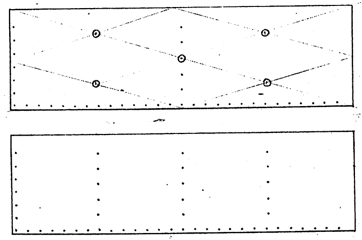
The number of sheets of sheathing
required for the Flying Cloud can be
determined roughly from a table presented by Butts81. This table was
prepared 3 by Captain Bardow, Superintendent of the East Boston Dry Dock, and
lists various ships and their sheathing requirements. The pertinent sections
of/this table have been presented as Table 19.
Table 19 - Sheathing Requirements
Ship Size Load-Water-Line Dead rise Length #
of Sheets
tons Forward Aft inches of
keel of
Sheathing
feet
Flying Fish 1505 18
19 20 190 2556
Morning Star 1800 20
20½ 21 205 2795
Star of Empire 2050 15
15½ 13 180 2310
Winged Racer 1767 19
20 26 193 2693
Comparing the dimensions of the Flying Cloud with those of the ships
given in the table it appears that the Flying
Cloud required in the neighborhood of 2700 sheets of sheathing.
Nails Table 20 presents the
data given by Butts82 for the number of composition sheathing nails
contained in one pound for lengths of ⅞
to 1½ inches in ⅛
inch increments. This data is for nails sold by H.N. Hooper & Company, 58
Commercial Street, Boston, Mass. However, in the BDA of March 5, 1851,
Fullerton & Raymond advertised only ⅞
to l¼ inch nails, which are presumably the sizes commonly used. These
different size nails were undoubtedly used to fasten different weight
sheathing. It is probable that four weights of sheet were used (22, 24, 26, 28
oz), corresponding to the four nail sizes (⅞,
1, 1⅛, l¼ inch).
Table 20- Number of Sheathing Nails per Pound
Length
of Nail Nails
per Pound
⅞ 230
1 190
1⅛ 186
1½
169
DavisDs105 states that a
composition sheathing nail was chisel-pointed with a large flat head, the head
being beveled on the underside. Butts gives composition nails as the fastenings
for yellow metal sheathing, while copper nails were used to fasten copper
sheathing.
Lindley states that in sheathing a
ship the copper was annealed (heated to p, dull redness and quenched) and then
beaten to shape with a mallet of a shape shown in Figure 60 (A); holes for the
nails were made with a punch (B).
Figure 60 - Sheathing Mallet and Punch
This section covers several terms
included in the text which are ambiguous or today are generally unknown.
Apartment
1) A suite or set of rooms; sometimes a single
room—Dictionary
2)
"The after part of the cabin, when required, can be converted into a separate apartment, by
curtains.” Shooting StarBDA
Between Decks
1) The
height from the upper side of one deck to the under side of the deck
above.— Fincham9
Bolts
1)
Common headed bolt had a small swell at the end.
2)
Tee-headed bolt--a segment of the head is taken off on each side L so as to
make it one way one-half the size it is the other. They were used for securing
chain plates that the chain plates might be m -t the bolts being driven out. In
this case they were called chain bolts.
3)
Clinched bolts were riveted.
4)
Forelocked bolts had a tendon and wedge in the end.
5)
Ring bolts had a ring in the eye of an eye bolt.
6)
Drift bolts were used for starting out other bolts.
7) Eye
bolts had an eye in one end (all the above descriptions from Fincham)
8) The
diameter of an eyebolt should be two and one-half times the diameter of the
iron it was made of. If a ring was put in this eye; its inside diameter was
five times the diameter of the iron.—DavisDp106
Cabin
1)
Nautical – A private room on a ship for officers or passengers.
2)
Navy – The quarters of the captain, etc. Dictionary
3)
“the forward cabin (was) separated from the other (aft) by a partition” -- DauntlessBDA
Cabin Class
A
class of accommodations in a passenger vessel, superior to tourist class,
inferior to first class. Cabin class was formerly used for first class. – Dictionary
Companion
The
hood or covering over the ladderway to the (captain's) cabin. Also the framing, formed with glass at
the upper parts or sides, over the captain's cabin, ward, or mess room, or
other officer's apartments for giving light – Fincham54
Composition—See Metal,
Composition
Cress Fastening
One
through bolt and two short fastenings in each frame.
Cross Fastening,
Double
Square fastening.
Dead Rise
1)
Perpendicular length included between the outer extremity of the half floor at
the dead flat and a horizontal line drawn from the base line.—Luce225
2) The
height of the end of the floor timbers above the base line; about two-thirds
the breadth of the vessel. – Butts76
First Class
The
highest class of accommodations in a passenger vessel, especially one having
three classes.—Dictionary
Gangway
“…the
deck of the forecastle and quarter decks are stopped short at the waste
amidships, which is thus left open; the passage to and from forecastle to
quarter being preserved by the deck at the sides of the ship going through and
forming what are called the gangways."—Peake"8
Hatchway
Passageway which goes between decks
to the hold – Fincham73
Depth of Hold
1)
"The depth of hold is taken from the top of the beam in the main hatch to
the top of the ceiling alongside of the keelson.. ."—Griffiths77,
Curtis27
2)
Upper side of lower deck beams to upper part of limber strake,—Fincham59
Ladderway
Passageway
that does not communicate with the hold.—Fincham75
Metal, Composition
According
to SmithA533 this is another name for brass. However, the Metals Handbook937
states that a bronze alloy containing 85% copper, 5% zinc, 5% tin, and 5% lead
is termed composition. This reddish bronze colored metal is used for general
castings requiring fair strength, soundness, and good machining properties.
Composition
to be of copper, zinc, and tin in such proportions as to give a tensile
strength of not less than 35,000 psi.—Hichborn5
Metal, Mixed
Composed
of copper and zink with a certain proportion of grain tin to give it sufficient
rigidity. – Fincham12,25
The
Metals Handbook gives only two copper-zinc-tin alloys:
Alloy Copper Zinc Tin
Admiralty metal 71.00 28.00 1.00
Naval Brass 60.00 29.25 0.75
Metal, Muntz
See
Metal, Yellow
Metal, Yellow
Nominally
60% copper, 40% zinc
Molding
The
convention used by McLean in his descriptions for the Boston Daily Atlas was
that in the nomenclature "15 by 20 inches", the first figure given
was the molded dimension while the second was the sided dimension.
Navel Timbers
"The
navel timbers, where they butt on the keel..."—OrientDBA
Quarter Deck
As the
cabin (trunk cabin built into a half poop deck) is small, "she has a
spacious quarter deck."—MysteryBDA
Siding
See
Molding.
Stateroom
A
cabin on shipboard.—Dictionary
Spirketting
"...that (inside planking)
placed-over the waterways is distinguished - by the. technical term of
spirketting."—Peake52
Wood
The
three principal kinds of ship timber were live-oak, yellow pine, and white
oak.—Griffiths175
Hard
Pine - generally considered the same as yellow pine.
Georgia
Pine - see Long-leaf Pine.
Long-leaf
Pine - according to Hall246 this is the same species as the
Southern Pitch Pine, the Pitch Pine, and the Yellow Pine. The tree grows from
Virginia southward, 60-80 feet high, with a diameter at the trunk of 2-4 feet.
The wood is course grained and weighs 40-50 lb/cu ft when seasoned.
Pitch
Pine - see long-leaf pine.
Southern
Pine – Fincham19 claims this to be the species pinus
australis or pinus palustris (see Long-leaf Pine).
Southern
Pitch Pine - see Long-leaf Pine.
Yellow
Pine – Fincham19 claims this to be the species pinus mitus
(see Long-leaf Pine).
A complete analysis of the
size of masts as exhibited in Table 21 would be complicated and probably
unmeaningtful. However, the trend of McKay's thinking can be surmised by a
cursory examination of this table. The following points will be noted
concerning sparring the first seven clipper ships built by McKay.
1) The
lengths of the main masts remained fairly constant.
2) The
mast diameters first increased then decreased.
3) The
lengths of the topmasts decreased slightly.
4) The
topmast diameters increased.
5) The
lengths of the topgallant masts decreased slightly.
6) The
diameters of topgallant masts increased substantially; however, the
mizzentopgallant decreased in the later ships
8)
Diameters of royals increased then decreased.
9)
Skysail mast length decreased.
10)
Diameters of skysail masts remained essentially constant.
It is obvious that McKay was
experimenting with sparring, the over-all trend being toward reducing the
length of the upper masts and increasing their diameters; then in later ships
reducing the diameters slightly. It is suggested that the reasoning which
brought these changes about was this: in order to reduce the loss of spars, the
lengths of the upper masts were reduced and the diameters of all masts
increased. Subsequently, however, the diameters were decreased because of the
stiffness of these large diameter masts.
Of course, the masts cannot be
considered apart from what they were designed to support, i.e., the yards. An
analysis of the trend in yard dimensions is more difficult than for masts.
Although not as obvious as for masts, in general, it may be said that both the
lengths and diameters of yards at first increased then decreased. Upper yards
had their diameter increased percentage-wise more than did the lower yards. It
could well be argued that the trends noted for masts were the result of the
changes in yard dimensions rather than any desire to make more substantial
masts for their own sake.
The important fact brought out by
this analysis is that McKay, and this is true of the other American builders of
the day, had no set sparring rules as did most of the foreign Guilders. They
experimented, and were not satisfied with what was produced, always feeling
there must be a better arrangement. The other point to make is that the early
ships were oversparred, as evidenced by the reduction in sparring of later ships.
An attempt was made to equate the
spar dimensions of the Flying Cloud
to fractions commonly used by the European builders. There was no evidence of
simple fractions and the three digit fractions which would be accurate are
unreasonable. This is a strong indication that proportions were made on- an
individual spar basis. Therefore, the dimensions not given in the BDA and the
taper of all spars has been derived from sources necessarily inconsistent with
the BDA dimensions.
It has been suggested that the
differences in size of spars among these ships could have been due to the
availability of timber rather than any conscious effort to change. There are
two facts which contradict this: first , the evident trend already discussed;
and second, the fact that it is known that at least four of the seven vessels
considered had "made" masts and there is strong evidence that the
others were of this type also.
Table 21 Dimensions of Masts and Yards