Henry Hall,
in his 1883 Models & Measurements notebook (Flying
Cloud material from the
notebook) said that the Flying Cloud’s decks were made from yellow and
pitch pine. The planks for the forecastle
& poop decks were 6 inches wide by 3.5 thick and the planks of the main
deck were 7 inches wide and 3.5 thick.
Campbell
reports that deck planks on clipper ships averaged 24’ long.[1]
He also reports that, on wooden ships, deck planks were fastened to each deck
beam they crossed with one or two wood treenails and, on iron hulled ships,
were fastened with bolts whose heads were sunk below the surface of the plank
and the hole plugged with a piece of wooden dowel. See figure 1.
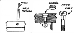
Figure 1: Deck fastening – from Campbell – China
Tea Clippers – page 147
On
the other hand, Crothers reports that planks fastened to the underlying beams
with spikes. First, 5/8 inch
diameter holes were bored part way through the planks and a smaller hole was
bored the rest of the way through the plank and into the underlying beam. After a spike was driven through the
plank with the head of the spike was tight against the bottom of the 5/8” hole,
the hole was plugged with a wooden plug, where the grain of the plugs was in
line with the grain of the deck planks. In most cases there were two spikes per
deck plank at each beam[2]
In any
case the fastenings were not all that visible, even on the actual ship. The hole plug in the plank was less
than an inch in diameter. At 1:96
scale, that would be a ring less than 0.01 inches in diameter. The treenail, dowel or plug were about
the same color as the plank. Thus, the fastenings were very hard, if indeed
possible, to see on the full-sized ship from more than a few feet away (see
figure 2 as an example) and, thus, nearly impossible to see in a scale
model.
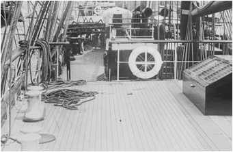
Figure 2: deck of Valhalla 1909?[3]
The deck
itself had a crown to it so that the water would run off. This was referred to as the “camber.”
According to Crothers, a typical deck camber was 6 inches at the widest point
of the deck[4]
The deck planks under deck houses were
continuous to keep the overall deck as water tight as possible. Of course, this was not the case for
the deck planks at hatches, since hatches have to penetrate the deck to be
useful.
The ends of the deck plank were
staggered to keep the deck as strong as possible. Under U.S. insurance rules, plank ends could not be closer
than 5 feet to each other length wise and there had to be at least 3 planks in
between planks that ended on the same beam.[5]
The edges of the deck planks, like the
edges of the hull planks, were slightly beveled to create a gap in which to
hammer strips of tarred oakum.
Crothers reports that the top of the gap was 1/16” per inch of plank
thickness.[6] Such a narrow slot is, of course,
impossible to see on a scale model, so there is no need to actually bevel the
plank edges. But the tarred calking would easily be seen as dark lines between
the planks. See figure 2 above for
an example. A common way for modelers
to create the visual effect of the calking is to rub the edge of the planks
with graphite (e.g., from a #2 pencil) before installing them. This produces a very thin dark line
between planks.
For my Flying Cloud model, I
spray painted one side of a basswood plank that had been sanded to be scale 6”
or scale 7” thick with a thin even coat of burnt umber paint. I then ripped the plank into strips,
each a little bit wider than the deck plank was to be thick, 3 ½ scale
inches (about 0.037 inches for 1:96 scale) to allow for sanding. I used burnt umber instead of black because
the tar used in the 1850s was Stockholm Tar, which was very dark brown rather
than black, and burnt umber is about the same color, although the difference
between burnt umber and black is hard to see at scale. For the ends of the planks, I chopped a
bunch of the strips into scale 24’ lengths, bundled them tightly together, and
sprayed one end with the burnt umber spray paint.
Deck planks were often trimmed (nibbed)
where they met the curved sides of a ship to avoid long narrow points that
could break easily and would be hard to secure. See figure 3.
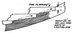
Figure 3 –
nibbed deck planks and a nibbing strake[7]
A
reasonable rule of thumb is that nibbing should be done when the length of
overlap with the nibbing
strake is more than twice the plank width. See
figure 4 for an example of nibbing from the forecastle deck of my Flying
Cloud model.
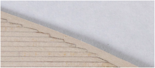
Figure 4 – nibbed edge of forecastle deck
For my
model, I cut the individual planks and the nibbing strake to shape then coated
the cut edges and end of the planks with burnt umber acrylic art paint to
represent the calking before gluing the planks to the deck.
I
determined that installing the deck directly onto the hull would be very
difficult, particularly if I wanted to nib the ends. Instead I made a template from the model itself and scanned
the template into a drawing program on my computer. I added a centerline and outlines for the deck furniture
then, using an ink jet printer, printed the result onto 1/64 inch aircraft
plywood. I then cut the plywood
following the outline. See figure
5.
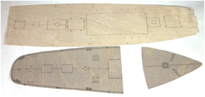
Figure 5 – templates for the decks
I then cut the nibbing strakes but did not glue them to the
template yet. I then carefully
glued a deck plank down the centerline, a plank with no paint on it to simulate
calking. Then, alternating sides,
I cut the deck planks along with the nibbing strakes as needed. I then glued the deck planks down with
the calking paint edge facing the center of the deck. I glued each nibbing
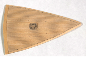
strake down after gluing the deck planks that intersected with it. See figure 6 for the finished
forecastle deck.
Figure 6 – finished forcastle deck
I used a
small syringe filled with white glue and with a #27 blunt needle to apply the
glue to back of the individual deck planks & the nibbing strake.
Most
decks of clipper ships in the mid 1800s were left unfinished and were scrubbed regularly and scraped with holystones, a type of sandstone, at the
end of voyages to make them look good.[8] I used a light pine stain on
basswood covered with a thin coat of satin polyurethane for the forecastle and
main decks on my Flying Cloud model. See figure 7 for an example of
holystoning.
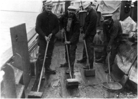
Figure 7 – crew
holystoning deck - 1929[9]
But
not all decks were left unfinished, some of the decks on higher end ships where
passengers could congregate were finished in a mixture of boiled linseed oil
and mineral spirits. This mixture
would turn the decks very dark, almost black in the sun. These decks were calked with white lead
to provide a contrast. See figure 8
for an example.
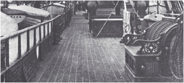
Figure 8 –
Cunard ship Russia – about 1870[10]
Even though I did not find any evidence
that the Flying Cloud had a dark deck I decided to make the poop deck,
where the passengers would have stayed, a dark deck because I thought it might
look nice. I used ebony for the deck planks & nibbing strakes.
To simulate the white lead caulking I used TerraSlate waterproof paper,
which is actually 5 mil plastic with a matt finish.
I was
able to find some ebony fingerboards for sale – they were about 1.5
inches wide by 16 inches long and about 4 mm thick, with one quite smooth
side. I tried sanding down the
thickness but found that the sanding belt immediately became hopelessly
clogged. So, I used a different approach.
I used contact cement to glue the TerraSlate paper to the smooth side of
an ebony fingerboard. I then
ripped the combination into strips that were the thickness that I wanted for
the deck and were whatever the thickness of the fingerboard was wide. Then I
ripped the resulting strips so that they were 6” (scale) wide, including the
TerraSlate paper. I used a 20 mil
thick fine tooth slotting blade to cut the ebony strips, it did not shatter the
ebony like coarser tooth blades did.
I then
chopped the strips into 42’ scale lengths and, also using contact cement, I
stuck a small piece of the TerraSlate paper on the end of each strip to
simulate the end calking. See figure 9.
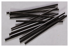
Figure 9 – ebony deck planks
Making
the ebony planks with nibbing was a bit more complex. After sanding the ebony to the right shape, more contact
cement & more TerraSlate paper was used to simulate
the calking in the nibbed area. See figure 10.
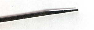
Figure 10 –
nibbed ebony deck plank
The final poop deck can be seen in
figure 11.
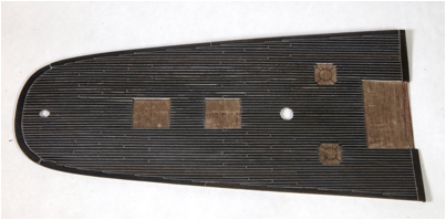
Figure 11 –
finished poop deck
All
of the decks were glued onto the hull, which had the camber built in, with
special gluing jigs. See figure
12.
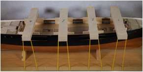
The
model with all decks installed can be seen in figure 13.
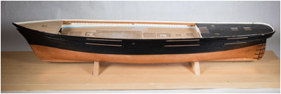
Figure 13 –
model with decks installed
Copyright
© 2021 Scott Bradner
2021-09-24